Veris Industries VWG-40 Install User Manual
Page 9
9
R S 4 8 5 — B A C n e t M S - T P w i r i n g .
An RS485, optically isolated port uses a 3-position, screw terminal connector and always operates as COM2. Wire to
this connector with shielded 8-22 AWG wiring (refer to the TIA/EIA-485 standard). The screw terminals (from left-to-
right) are shield, plus (+), and minus (–).( VWG-40-MSTP only )
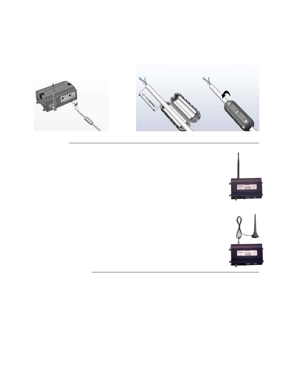
The supplied ferrite in the VWG packaging needs to be installed on the MS-TP wire in a specific way for FCC
compliance. Place MS-TP wire into the provided ferrite as shown in diagram below. Make sure to follow the
placement dimension. Close and snap the ferrite casing as shown.
Wire MS-TP cable into MS-TP RS-485 connector.
Antenna installation
C o n t r o l l e r m o u n t e d a n t e n n a ( V W G - W A )
All VWG-40 are supplied with a controller-mounted antenna. The antenna is shipped loose in the
controller main packaging box.
This installation type is to be used only when the controller ( and antenna ) is not installed inside
a closed metal enclosure and that clear reception is expected.
Gently screw the antenna into the antenna connector at the top of the VWG. Do not over tight the
antenna.
R e m o t e m o u n t e d a n t e n n a ( V W G - R A )
If a remote mounted antenna is required because of the location of the VWG, a separate antenna
can be ordered. Part number VWG-RA
This installation type can typically be used when the controller is installed inside a closed metal
enclosure.
Gently screw the female connection of the remote antenna into the VWG. Remote antenna has a
weighted magnetic base for metal surface mounting. Wire length is 1.5 M ( 4.9 Ft )
Power Up and Initial Checkout
Procedure
- Initial power up and checkout
1. Connect the Backup Battery.
2. Apply
Power.
3. Check the Status LEDs.
1 ) C o n n e c t t h e B a c k u p B a t t e r y
With the cover removed from the VWG (see “Removing and Replacing the Cover,”), locate the red and black wires
coming from the backup battery, with 2-position connector plug. Plug the connector into the battery connector on the
bottom board (below option slot 2 area). The connector is keyed—you cannot insert it incorrectly. The red (positive)
connection should be the furthest from the two 30-pin option modules connectors.
For more details on the backup battery, see “About the Battery”.