Veris Industries VWG-40 Install User Manual
Page 8
8
VWG-PS-AC 120 Vac Wall mounted power supply module
Both the U.S. and International models of wall power modules are self-contained switching power supplies designed to
plug into a standard building power receptacle of appropriate voltage. To supply power to the VWG, you then simply plug
the coaxial connector from the VWG-PS-AC into the coaxial power connector on the VWG base board.
VWG-PS-DC Panel mount 24Vac-power supply module
Using the VWG-PS-DC module lets you power the VWG from a standard Class 2 24Vac transformer. The VWG-PS-
DC module provides power isolation (it makes no difference if the transformer output is “floating” or has one side tied to
ground). Therefore, you can use an existing nearby transformer, providing that it has 5 VA capacity available to power
the VWG.
P o w e r W i r i n g
Only VWG-PS-DC and VWG-PS-AC power supply with factory installed ferrite
on the power cord can be used with the VWG. The usage of another non-
approved power supply may void the FCC compliance of the VWG and wireless
thermostats.
C o n n e c t p o w e r c o r d a s s h o w e d i n t o coaxial connector.
Do not plug the coaxial connector from the power supply into the
VWG until all other mounting and wiring is completed. See “Power
Up and Initial Checkout,” section.
C o m m u n i c a t i o n s W i r i n g
Connect communications wiring to the VWG using either Net1, Net2 or the RS-485 connection based on VWG model
used and configuration.
Note
Prior to connecting cables, provide strain relief for them to prevent damage to the controller.
Ethernet— B A C n e t o v e r I P w i r i n g
Two, female 10/100-Mbit Ethernet connections are provided on the VWG. These are RJ-45 connectors labeled NET2 and
NET1. Use a standard Ethernet patch cable for connecting to a hub or Ethernet switch. An activity LED for each Ethernet
port is visible and labeled “NET2” and “NET 1” on the cover.
Note Typically, you only use NET1 (primary port), unless you have a specific application for isolating a driver’s
network traffic to a separate IP address (and LAN) using NET2. In all cases, port selection can be changed
and is dependent of configuration made using the VWG configuration tool.
The packing slip accompanying the VWG will provide the “factory-shipped” IP settings for both NET1 and NET2. Refer
to the document LIT-VWG-40-SETUP-Exx for more information for details on the default IP address and how to
change it. ( VWG-40-IP only )
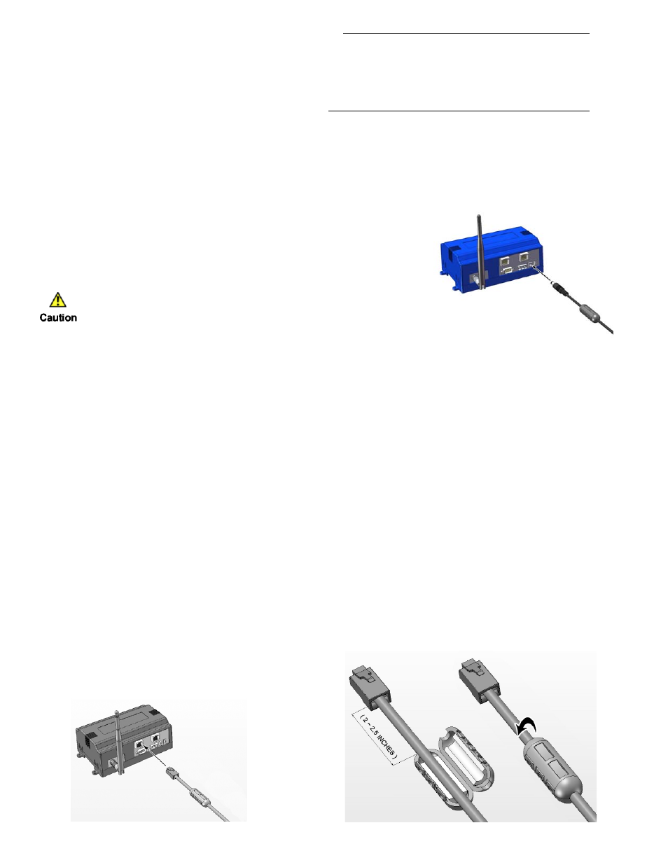
The supplied ferrite in the VWG packaging needs to be installed on the IP wire in a specific way for FCC
compliance. Place IP wire into the provided ferrite as shown in diagram below. Make sure to follow the placement
dimension. Close and snap the ferrite casing as shown.
Wire IP cable into NET1 or NET2 as per configuration.