Veris Industries VWG-40 Install User Manual
Page 7
7
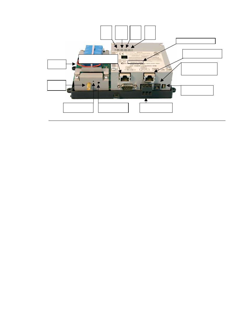
Board Layout
Figure below shows the location of LEDs, connections and other features of the VWG with the cover removed.
Wiring Details
See figure above to locate connectors and other components on the VWG controller. Make
connections to the VWG in the following order.
1. Connect earth-grounding wire with spade connector from the earth ground lug on the VWG. See “Grounding” for
details.
2. Prepare power wiring (leave the unit powered off). See “Power Wiring” for details.
3. Connect communications wiring. See “Communications Wiring,” page 14 for ports available on the VWG base unit.
For ports on any installed option board (LON, RS-485, modem) see the specific mounting and wiring guide for any
additional details.
4. Connect the backup battery to the VWG battery connector, and apply power to the unit. See “Power Up and Initial
Checkout,” page 17.
G r o u n d i n g
Use an earth ground spade lug (0.187") on the base of the VWG for connection to earth ground. For maximum
protection from electrostatic discharge or other forms of EMI, you should connect this to earth ground using a #16 AWG
or larger wire. Keep this wire as short as possible.
If desired, you can use the wall mount VWG-PS-AC 120 Vac power supply in your office ( when initially commissioning
the VWG ), and then install the panel mount 24 Vac VWG-PS-DC power supply at the job. The following sections provide
more details:
• VWG-PS-AC ( 120 Vac Wall mounted power supply module )
• VWG-PS-DC ( Panel mount 24Vac-power supply module )
Battery
connector
Ethernet IP connection
RJ-45, Net1
MS-TP RS-485
connection, COM2
Coaxial power
connector for wall
mounted power module
Earth ground spade
lug connector
VWG wireless card
reset button
VWG wireless card
Com status LED
Net1
status
LED
Net2
status
LED
BEAT
status
LED
SYS
status
LED
Antenna
connector
Ethernet IP connection
RJ-45, Net2
Location of serial number