Veris Industries VWG-40 Install User Manual
Page 11
11
Using Status LEDs
The VWG controller includes several LEDs that can help determine the status of the unit. They are located in two
places: the top of the controller (visible through the cover), and for serial ports, on the bottom board (only with cover
removed). From left-to-right these LEDs include:
• Ethernet Ports
• Heartbeat
• System
• Wireless card communication status
E t h e r n e t P o r t s
Each Ethernet port (“NET2”, “NET 1”) has one green LED, visible on the top cover. A “NETx” LED indicates activity on
that port as follows:
• Off—No Ethernet link is made
• On—Ethernet link is present, but no activity on the LAN
• Blinking—Ethernet link is present with data activity on the LAN.
Beat
The “BEAT” LED is located to the right of the Ethernet status LEDs, and is yellow. Under normal operation, this LED
should blink about once per second. Blink patterns differ as station activity varies, but any pulse rate from once per
second to 10 blinks per minute usually indicates normal operation. If the heartbeat LED stays on constantly, does not
light, or blinks very fast (more than once per second), contact System Engineering for technical support.
S y s t e m
The “SYS” LED is located to the right of the heartbeat (“BEAT”) LED, and is green. This LED provides a CPU machine
status check, and should remain lit whenever the VWG is powered. If the SYS LED does not light while power is applied,
contact technical support for assistance.
Wireless card communication status
The Wireless card communication status is located right beside the wireless antenna connection on the VWG. This LED
provides a simple diagnostic status of the Viconics wireless network.
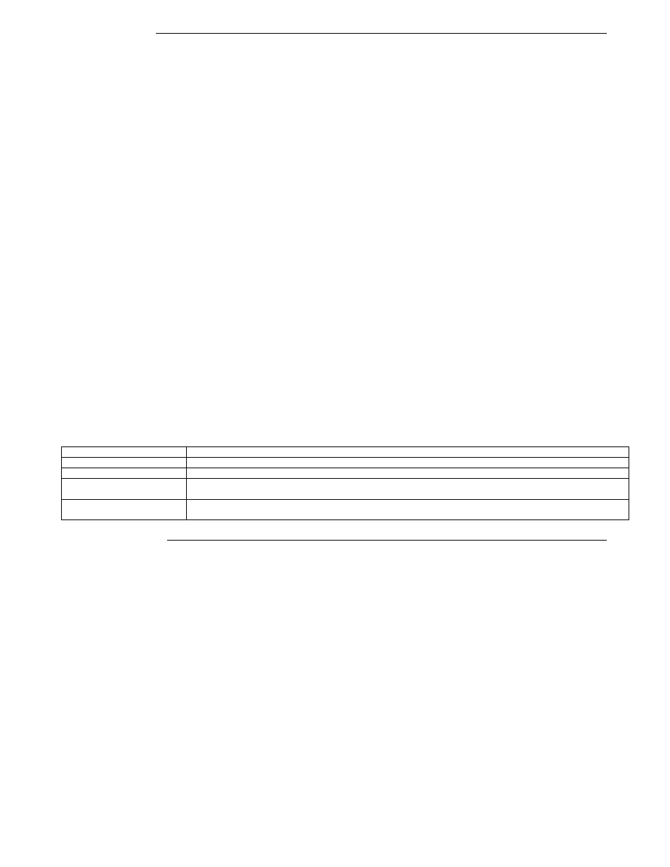
1 x 200ms short blink
Power on
2 x 200ms short blinks
Power on and card memory initialized properly
3 x 200ms short blinks
Power on, card memory initialized properly and serial communication with VWG main board active
4 x 200ms short blinks
Power on, card memory initialized properly, serial communication with VWG main board active and wireless
networks started successfully
4 x 200ms short blinks and
1 x 1500ms long blink
Power on, card memory initialized properly, serial communication with VWG main board active, wireless
networks started successfully and wireless communication with thermostats active
Maintaining the VWG
This section provides information on the following topics:
1. Cleaning
2. Required Battery Maintenance
3. Replacement
Parts
4. Replacing the VWG base assembly
5. Returning a Defective Unit
1 ) C l e a n i n g
If dust or metal filings are present inside the unit, clean with vacuum or compressed air. Otherwise, no cleaning inside the
unit is required. Optionally, if the cover becomes dirty, you can wipe it with a damp cloth and mild detergent.