Veris Industries VWG-40 Install User Manual
Page 5
5
Mounting
Mount the VWG in a location that allows clearance for wiring, servicing, and antenna removal.
Environmental Requirements
Note the following requirements for the VWG mounting location:
• This product is intended for indoor use only. Do not expose the unit to ambient conditions outside of the range of
0ºC (32
º
F) to 50
º
C (122
º
F) and relative humidity outside the range 5% to 95% non-condensing (pollution degree 1).
• If mounting inside an enclosure, that enclosure should be designed to keep the unit within its required operating
range considering a 20-watt dissipation by the controller. This is especially important if the controller is mounted
inside an enclosure with other heat producing equipment.
• Do not mount the unit:
– In an area where excessive moisture, corrosive fumes, or explosive vapors are present.
– Where vibration or shock is likely to occur.
– In a location subject to electrical noise. This includes the proximity of large electrical contractors,
electrical machinery, welding equipment, and spark igniters.
Physical Mounting
The following information applies about physically mounting the unit.
• You can mount the VWG in any orientation. It is not necessary to remove the cover before mounting.
• Mounting on a 35mm wide DIN rail is recommended. The VWG unit base has a molded DIN rail slot and locking
clip, as does the VWG-PS-DS 24Vac power supply module.
• If DIN rail mounting is impractical, you can use screws in mounting tabs on the VWG
The following procedure provides step-by-step DIN rail mounting instructions for the VWG. Mount the VWG prior to
mounting any accessory items.
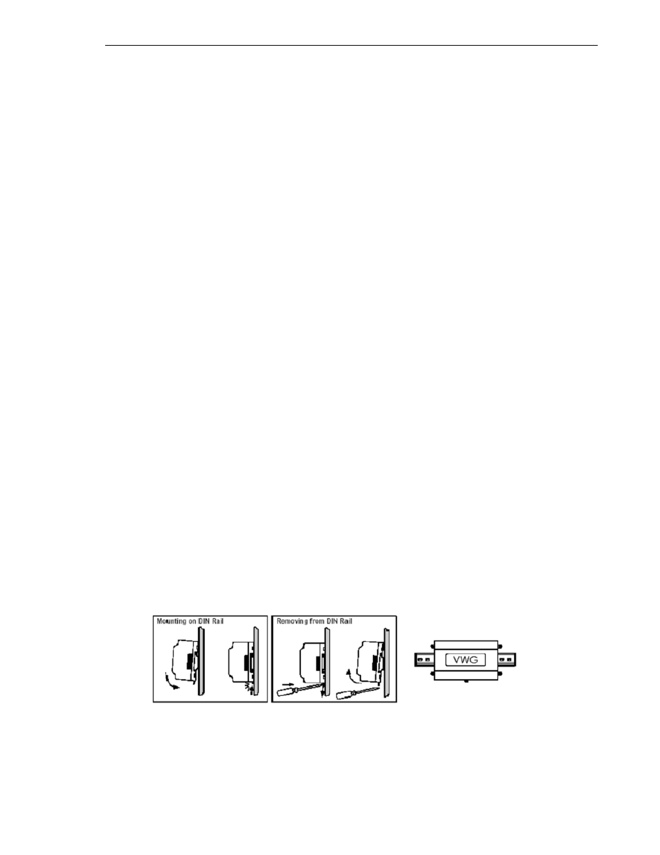
P r o c e d u r e 1 - T o m o u n t o n D I N r a i l
Step 1 Securely install the DIN rail using at least two screws, near both ends of the rail.
Step 2 Position the VWG on the rail, tilting to hook DIN rail tabs over one edge of the DIN rail
Step 3 Pull out the DIN rail clip and push down and in to force the DIN rail clip to snap over the other edge of the DIN
rail.
Step 4 To prevent the VWG from sliding on the DIN rail, secure with clips provided by the DIN rail vendor, or place a
screw in one of the four mounting tabs in the base of the VWG.
Step 5 If VWG-PS-DC 24 Vac power supply is used, mount onto the DIN rail in the same manner.