Technical data – M&C TechGroup SP2400-H Data sheet User Manual
Page 2
M&C TechGroup Germany GmbH • Rehhecke 79 • 40885 Ratingen • Germany
[email protected] • www.mc-techgroup.com • Fon +49 2102 935-0 • Fax +49 2102 935-111
2.1
Technical Data
Technical specifications and illustrations are without
obligation, subject to modifications. 10.04/06.06
Gas Sample Probe Version
SP2000
SP2000-H
SP2300-H
SP2400-H
Part No.
20S1000
20S2000
20S3000
20S3500
Protective cover
no
yes
yes
yes
Degree of protection
IP54 EN60529
Filter housing material
Stainless steeel 316*
PTFE
Titanium
Sealing materials
FPM* /7aT** = PTFE /H320** = graphite
Probe flange sealing material
Novapress
Insitu probe tube/prefilter
Optional
Sample pressure max.
0,4-6 bar* abs., /7aT**= 2 bar abs., /HP** = 25 bar abs.
0,4-2 bar abs.
0,4-6 bar abs.
Ambient temperature
20 °C to +180 °C
-20 °C to +60 °C*** /PT100, /Fe-CuNi, /Ni-CrNi** = -20°C to +80°C
Filter chamber volume
120 cm3
Filter element, porosity
S-2K150= Ceramic*, 2micron, /F-0, 1GF150= Glass fibre**, 0,1 micron, /FW= Spun glass**
Thermostat, Temperature adjustment
0-180°C* /H320**= 0-320°C /PT100** /Fe-CuNi** /Ni-CrNi**
Ready for operation
after 40min /H320** = after 60min
Low temperature alarm contact*
Contact rating: 250V, 3A~, 0,25A= Alarm point: ∆T 30°C
Sample gas outlet connection
1x 1/4“ NPTi* tube connectors ø 6, 8 or 10 mm** /H320**= 6 mm
Backflush/Test gas connection
1/4“ NPTi* /R**, /H320**= tube ø 6 mm
Power supply
230V 50/60 Hz, 800W /115V** = 115V 60Hz, 800W (fuse protection 10A)
Electrical connections
Terminals max. 4mm2, 2x PG 13,5 cable gland
Electrical equipment standard
EN 61010, EN 60519-1
Mounting flange
DN65 PN6-B
>DN or ANSI possible** /HP** = DN50 PN25
Mounting flange material
SS316Ti
PTFE
Titanium
Weight
7 kg*
15,4 kg*
15,4 kg*
14,5kg*
*
Standard
**
Options (/H320 not for SP2300-H, /7aT** not for SP2300-H and SP2400-H)
*** In case of higher ambient temperatures use option PT100 (Part No. 20S9025) or thermocouple Fe-CuNi respectively Ni-CrNi (Part No. 20S9027 resp. 20S9028) instead of the thermo-
state controller. Then, an additional electronic temperature controller (see data sheet 2-5.1) is necessary.
∆P and T90 at flow of:
100
200
500
1000
1500
3000 (only /HF)
Nl/hr
∆P with new filter element S-2K150/GF150
0,007
0,011
0,02
0,058
0,135
0,240/0,225
bar
T90-time for SP2000-H without tube
6
3,5
1
<0,5
<0,5
<0,5
s
Differential pressure and T90-time
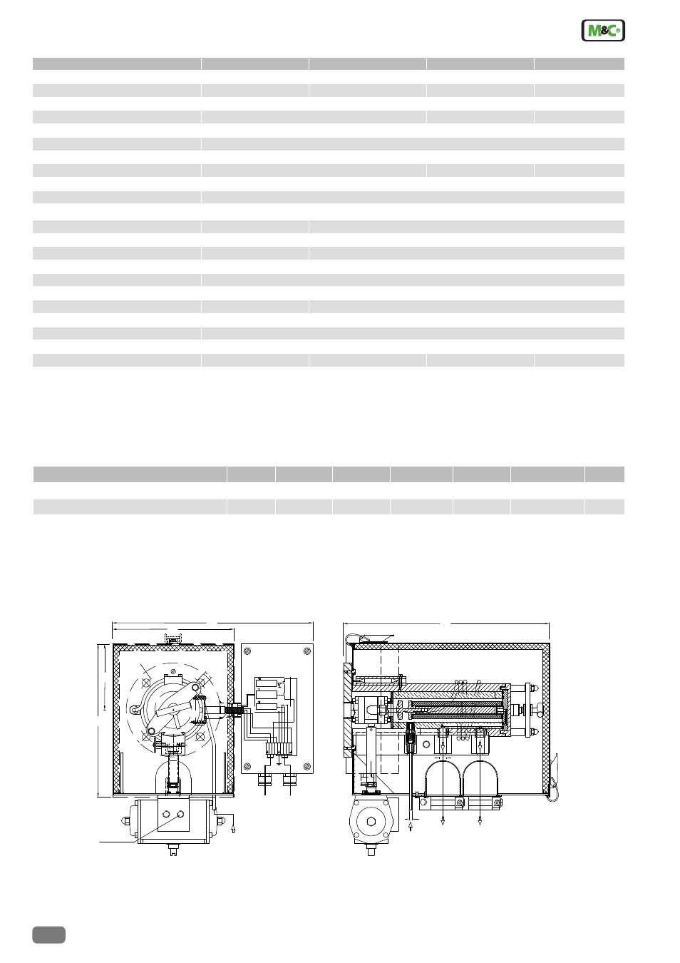
Dimensions
SP2000-H basic version with options (Examples)
Dimensions in mm
260
(115V,60Hz)
230V,50Hz
2
N
1
L 'L
5
3 4
6 8
7
9
207
340
110
T >+30°C
0-180°C
T <-30°C
345
G 1/4" i
Actuator
pressure inlet
(test gas)
Blow back
Alarm contact
Power
Tset
(Blow back)
Test gas
Sample gas
outlet *
Second sample
gas outlet
o
u
130
14
6
1/4"NPTi
*Standard