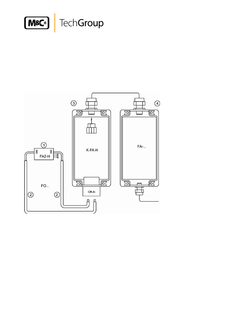
Description, Figure 1, Complete optical flow monitoring system – M&C TechGroup FA1-H Operator's manual User Manual
Page 9
9
Gas sampling and gas conditioning technology
5-6.15ME
9
DESCRIPTION
The M&C flow monitoring unit FA1-H-.. consists of 4 sub-assembly modules:
1. the patented sensor head FA2-H,
2. the 2 light guides FO.. for monostable function
3. the K-FA-H pre-amplifier
4. the electronic controller FA-1.1 or FA-1.4 (see data sheet FA-.., K-FA 5-6.10.2)
Figure 1
Complete optical flow monitoring system
The sensor head FA2-H is assembled on e.g. the FM1-H flowmeter by means of a pressure screw
with its stationary open prism to the measuring glass. Assembly is simple and does not require any
disassembly of the flow-measuring glass.
The FO1 light guide is supplied with a standard length of 600 mm. Light guide FO3 (900 mm long) and
FO2 (1200 mm long) can be supplied for greater length requirements. The angled light-guide ends are
fixed into the FA2-H sensor head with one pressure screw each. Two light-guides are needed for the
monostable function. By use of the pre-amplifier K-FA-H a distance of 200 meters between the flow
meter and the electronic controller FA-1.. (see data sheet 5-6.10.2) is possible without problems.
The LED emitters' light beam passes through the FO .. light guides and falls upon the photo-transistor
through e.g. the FM1-H flowmeter measuring glass. As soon as the float breaks the light beam, the
photo-transistor is blacked out. The FA-1.. electronic controller analyses this changed status
accordingly. By the monostable version a MIN alarm function in the lowest sensor setting position is
guaranteed.