Electrical connections, Figure 3, Mounting of the heated sample tube sp30-h../sp35-h – M&C TechGroup SP35-H... Operator's manual User Manual
Page 11
11
Gas sampling and gas conditioning technology
2-1.9.6MD
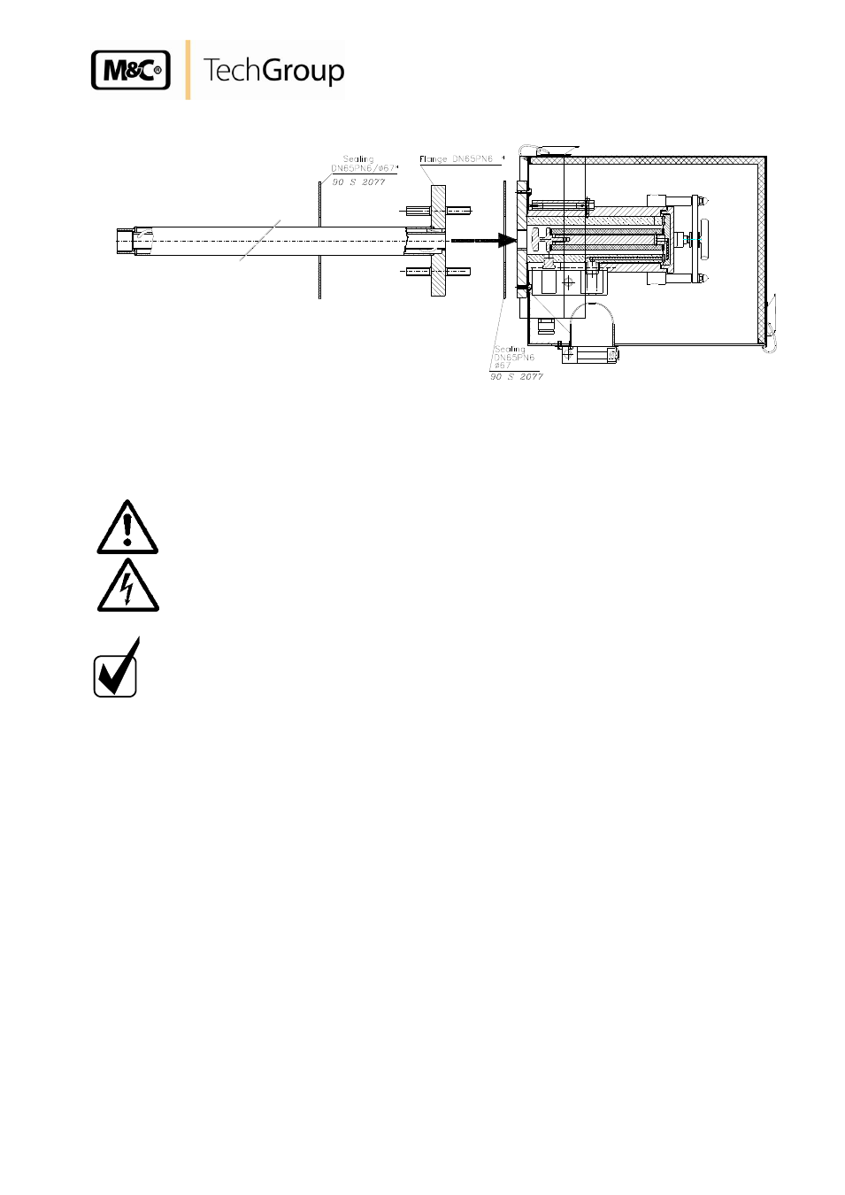
Figure 3
Mounting of the heated sample tube SP30-H../SP35-H..
12
ELECTRICAL CONNECTIONS
W A R N I N G !
When connecting the equipment, please ensure that the supply
voltage is identical with the information provided on the model
type plate.
N O T E !
Attention must be paid to the requirements of IEC 364 (DIN VDE
0100) when setting high-power electrical units with nominal
voltages of up to 1000 V, together with the associated standards
and stipulations.
In any case we recommend the use of temperature resistant cable !
A main switch and matching fuse must be provided externally!
The main circuit must be equipped with a fuse corresponding to
the nominal current (over current protection); for electrical details
see technical data.
Remove lid of the connection box. In the lid there is also the electrical wiring plan.
The used cables for the connection of the heating must have an outer diameter of 6-12mm
corresponding to the clamping range of the cable glands to guarantee protection class IP54.
Insert the power cable (min. 3 x 1,5 mm
2
) coming from the external temperature controller
through the cable gland and connect it at the corresponding terminals 2, 5 and 6.
Insert the temperature sensor cable through the other cable gland and connect it to the
terminals 7 and 8.
Remount lid.