3 system power-up, System overview – Garmin G950 Tecnam 2006T User Manual
Page 19
190-01146-00 Rev. A
Garmin G950 Pilot’s Guide for the Tecnam P2006T
7
SYSTEM OVERVIEW
SY
STEM
O
VER
VIEW
FLIGHT
INSTRUMENTS
EIS
AUDIO P
ANEL
& CNS
FLIGHT
MANA
GEMENT
HAZARD
AV
OID
ANCE
AFCS
ADDITIONAL
FEA
TURES
APPENDICES
INDEX
1.3 SYSTEM POWER-UP
NOTE:
Refer to Appendix A for system-specific annunciations and alerts.
The G950 System is integrated with the aircraft electrical system and receives power directly from electrical
busses. The PFD, MFD, and supporting sub-systems include both power-on and continuous built-in test features
that exercise the processor, RAM, ROM, external inputs, and outputs to provide safe operation.
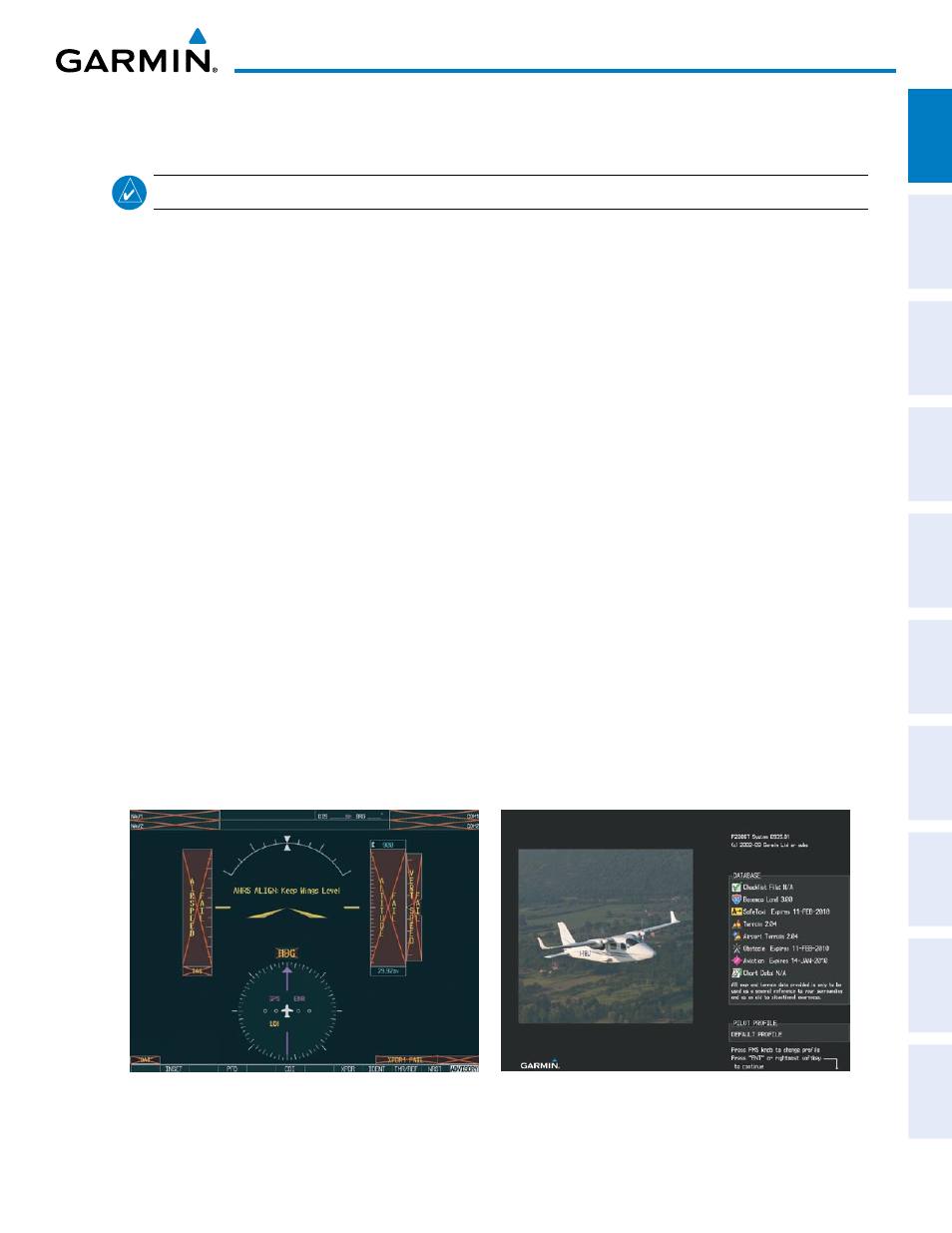
During system initialization, test annunciations are displayed, as shown in Figure 1-4. All system annunciations
should disappear typically within the first minute of power-up. Upon power-up, key annunciator lights also
become momentarily illuminated on the Audio Panel, the MFD Control Unit, and the display bezels.
On the PFD, the AHRS begins to initialize and displays “AHRS ALIGN: Keep Wings Level”. The AHRS should
display valid attitude and heading fields typically within the first minute of power-up. The AHRS can align itself
both while taxiing and during level flight.
When the MFD powers up, the Power-up screen (Figure 1-5) displays the following information:
• System version
• Copyright
• Land database name and version
• SafeTaxi database information (see Additional Features)
• Terrain, Airport Terrain, Obstacle, and Aviation database name, version, and effective dates
Current database information includes valid operating dates, cycle number, and database type. When this
information has been reviewed for currency (to ensure that no databases have expired), the pilot is prompted to
continue.
Pressing the ENT Key (or right-most softkey) acknowledges this information, and the Navigation Map Page is
displayed upon pressing the key a second time. When the system has acquired a sufficient number of satellites to
determine a position, the aircraft’s current position is shown on the Navigation Map Page.
Figure 1-4 PFD Initialization
Figure 1-5 Example MFD Power-up Screen