2 > connection standard – Acnodes MCS User Manual
Page 4
< 1.2 > Connection Standard
1)
Computer to LCD display connection standard
- Conducts bi-directional communication using serial RS232.
- Use three signal wires of TxD, ( pin 2 ), RxD ( pin 3 ) and GND ( pin 5 ), among the RS232
standard wires, as Fig. 2-1.
- Use DTR ( pin 4 ), RTS ( pin 7 ) for hot-plug detect.
- The distance between the PC computer to LCD display is limited 15m.
2)
LCD display to LCD display connection standard
- Conducts bi-directional communication using CAN bus
- A maxim um of 64 LCD display units can be dais y chained to one CAN bus, up to 1,000 meters.
- The distance between LCD Displays is limited 300 meters via Cat 5/ 6 cable.
3)
Command communications
The CAN bus requires the MCS module of LCD display registration by sending command < 0x01 >
to add or remove the LCD display(s) from the CAN bus before com mand com munications. Please
refer to page 6 for m ore details.
All communications are conducted in the form of hexadec imal number, and the checksum c alculation
method as below :
Total =
Command + ID + Val1 + Val2 + Val3 + Val4 + Val5 + Val6;
Checksum =
256
– Total;
* Unsigned character of Chec ksum, Total=0;
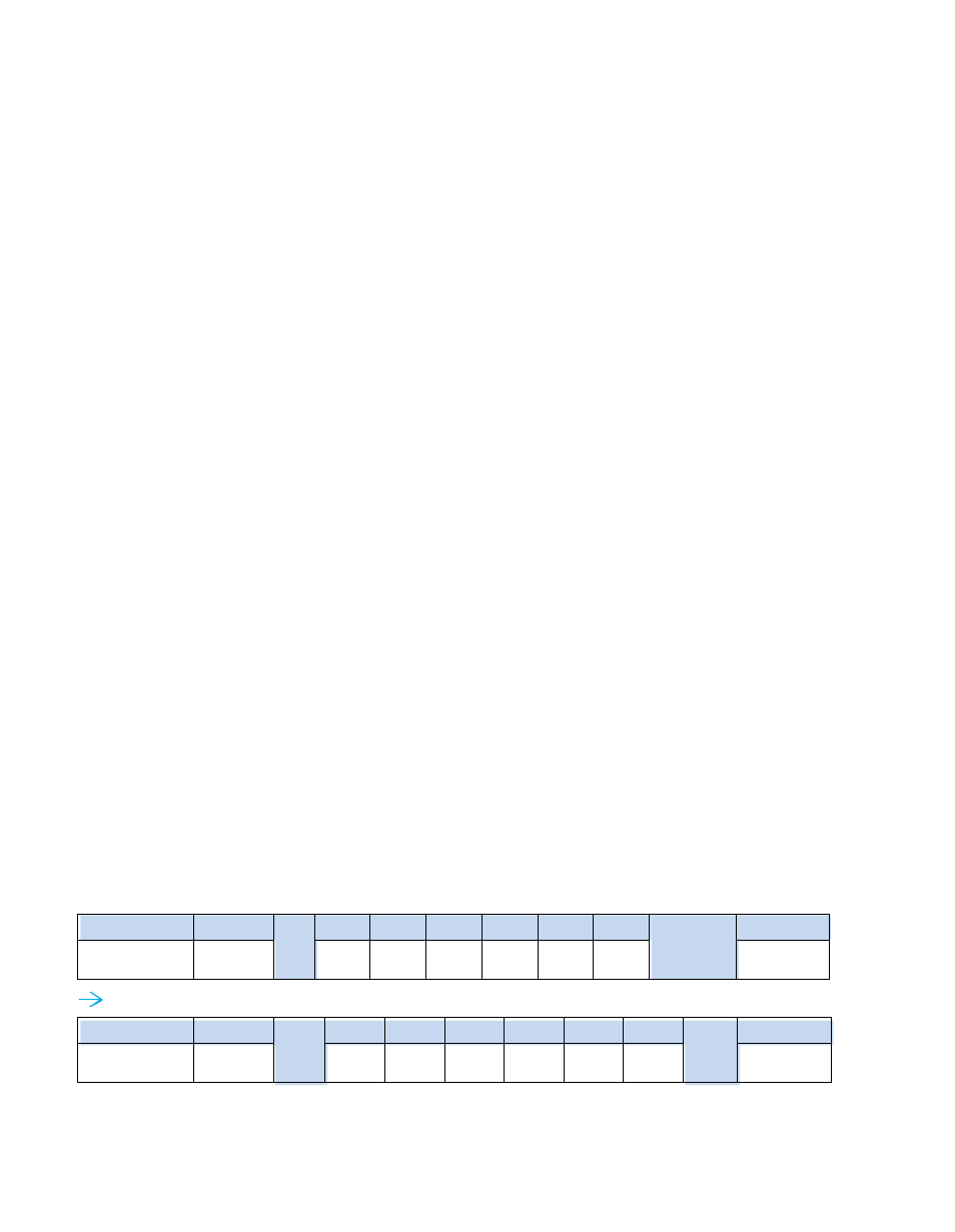
Get Power Status
( e.g. Power ON & ID=1 )
Header
Command
ID
Val 1
Val 2
Val 3
Val 4
Val 5
Val 6
Checksum
Footer
0x4D,
0x43,0x06
0 x04
Power
0x00
0x00
0x00
0x00
0x00
0x0D, 0x0A
Header
Command
0x01
Val 1
Val 2
Val 3
Val 4
Val 5
Val 6
0xFA
Footer
0x4D,
0x43,0x06
0 x04
0x01
0x00
0x00
0 x00
0x00
0x00
0x0D, 0x0A
Here, each set functions according to the com mands received and responds with ACK at the same time.
Therefore, the operation of each set s hould be checked after this process.