Operation leds, Table3-3 hub operation leds, Fan fail – 3Com 100 TX User Manual
Page 36: Amber, One or both of the two internal fans have failed, Overtemp, The internal temperature exceeds 158° f (70° c), Collision, Green, The segment is experiencing collisions
3-12
C
HAPTER
3: M
AKING
FMS 100-TX H
UB
C
ONNECTIONS
Operation LEDs
Table 3-3 interprets the meaning of the hub operation LEDs.
Unit Digital Display
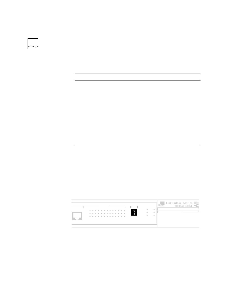
The front panel unit digital display (see Figure 3-11) provides a numeric
designation for each component in a hub stack, including a Management Unit
if one is present. Unit numbers are assigned dynamically as the units are
plugged into the stack. The Management Unit ID is assigned after the
Power-On Self-Test (POST) has run. The number 1 indicates the device that has
no other unit above it; in other words, the hub (or Management Unit) that is on
the top of the stack and connected by a hub expansion cable to the
component immediately below it.
Figure 3-11 Unit Digital Display
Table 3-3 Hub Operation LEDs
LED
Color
Status
Meaning
FAN FAIL
Amber
ON
One or both of the two internal fans
have failed.
OVERTEMP
Amber
ON
The internal temperature exceeds 158
°
F
(70
°
C).
COLLISION
Green
ON
The segment is experiencing collisions.
CLS II (Class II)
OFF
The FMS 100-TX Hub does not support
Class II configuration. This LED is
nonfunctional.
CLS I (Class I)
Green
ON
The FMS 100-TX Hub supports Class I
configuration, which means that only
one repeater or hub stack can be used
between two end stations.
PWR (Power)
Green
ON
The hub is receiving power.
12x
UNIT
STATUS
1 2 3 4 5 6 7 8 9 10 11 12 13
ACTIVITY
LINK
PARTITION
CLSII
3C250-TX/
Ι
CLSI
PWR
FAN FAIL
OVERTEMP
COLLISION
®