Hub to node, Figure3-1 linkbuilder fms 100-tx hub supporting 1, Hub to node 3-2 – 3Com 100 TX User Manual
Page 26: Fms 100-tx h, Hapter, Aking, Onnections
3-2
C
HAPTER
3: M
AKING
FMS 100-TX H
UB
C
ONNECTIONS
Hub to Node
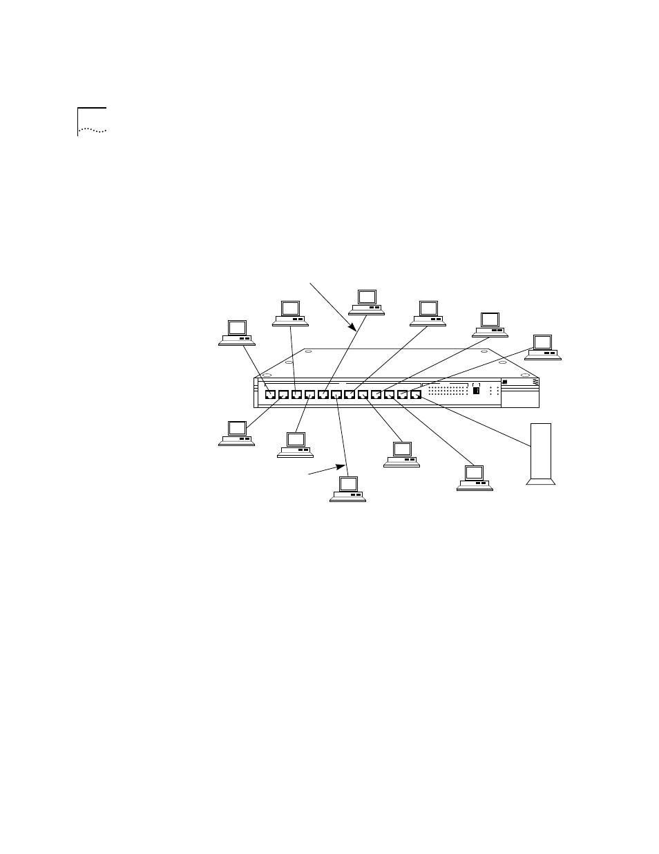
Once installed, the hub can support up to 12 end node connections.
Figure 3-1 shows 11 PCs and one server connected to the RJ-45 ports on
the hub’s front panel. You can connect any combination of PCs, servers, and
other hubs to the 12 RJ-45 ports. (The thirteenth port permits an additional
connection through the transceiver interface module located on the hub’s
rear panel. See the section “Installing the Transceiver Interface Modules” in
Chapter 2.)
Figure 3-1 LinkBuilder FMS 100-TX Hub Supporting 11 Users and a Server
The maximum allowable distance between the hub and a PC, server, or
other device is 100 meters of Category 5 UTP cable. The UTP cable used for
hub-to-node connections is a straight-through connection. That is, no
crossovers should be present. The pin assignments for a straight-through
cable are shown in Figure 3-2. Refer to Chapter 4 for cabling details.
®
100BASE-TX Hub
1x
2x
3x
4x
5x
6x
7x
100BT
STATUS
8x
9x
10x
11x
12x
1 2 3 4 5 6 7 8 9 10 11 12
13
ACTIVITY
UNIT
LINK
PARTITION
CLSII
3C250-TX/
Ι
CLSI
PWR
FAN FAIL
OVERTEMP
COLLISION
LinkBuilder FMS 100
Twisted-pair
cable
LinkBuilder
FMS 100 Hub
Server
100 meters maximum