Figure3-2 pin assignments for straight-through ca, Figure3-3 rj-45 connector pin assignments, Wn in figure 3-2 – 3Com 100 TX User Manual
Page 27: Figure 3-3 rj-45 connector pin assignments, Td – td + rd – rd
Making Network Connections
3-3
Figure 3-2 Pin Assignments for Straight-Through Cabling
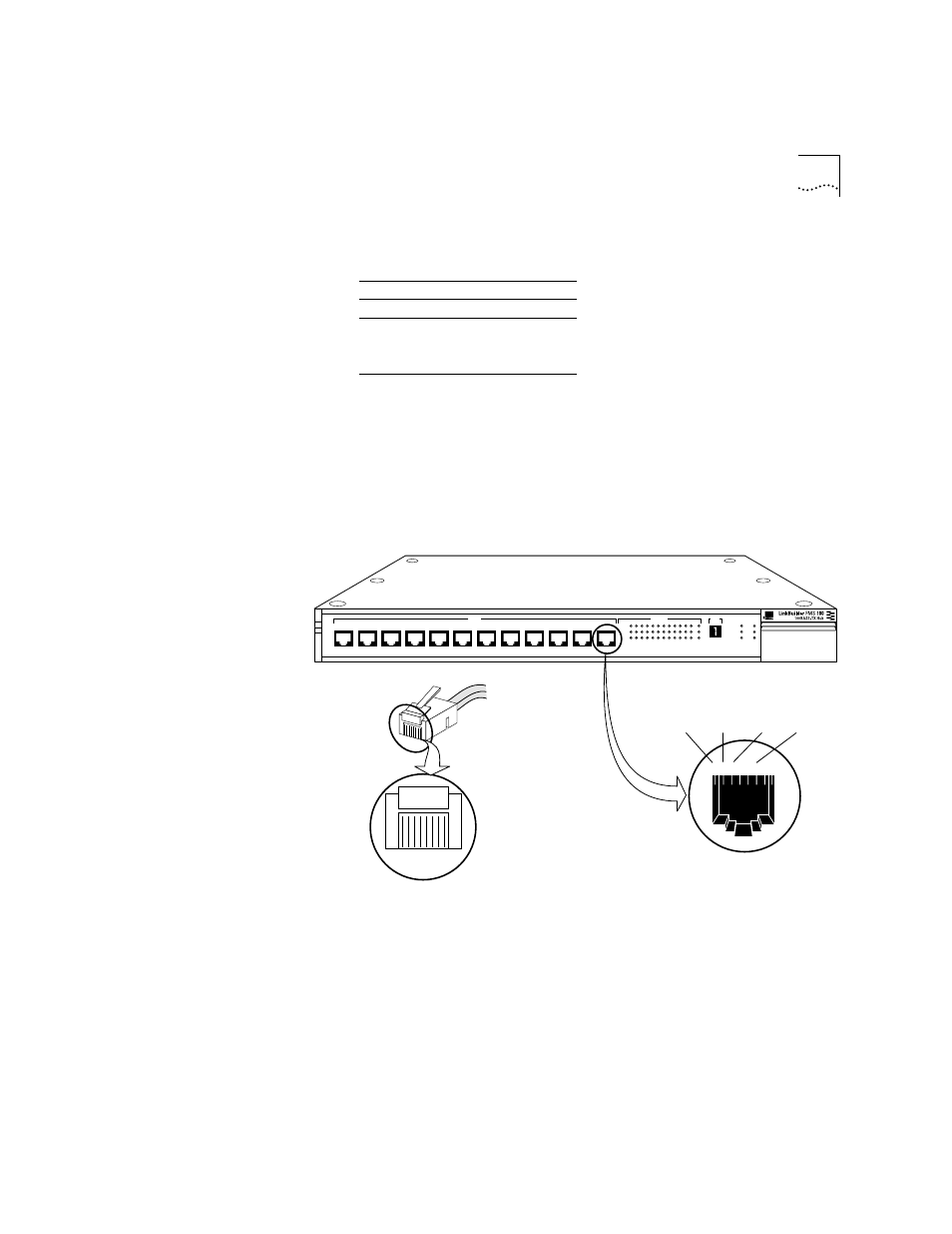
The pin assignments for the 100BASE-TX transceiver interface module are
the same as the pin assignments for the RJ-45 ports on the hub’s front
panel. Figure 3-3 shows the RJ-45 connector pin assignments.
Figure 3-3 RJ-45 Connector Pin Assignments
1
2
3
4
5
6
7
8
Adapter
Hub
1
2
3
4
5
6
7
8
1
12345678
2 3 4 5 6 7 8
TD –
TD +
RD –
RD +
®
1x
2x
3x
4x
5x
6x
7x
100BT
STATUS
8x
9x
10x
11x
12x
1 2 3 4 5 6 7 8 9 10 11 12
13
ACTIVITY
UNIT
LINK
PARTITION
CLSII
3C250-TX
CLSI
PWR
FAN FAIL
OVERTEMP
COLLISION