Analog programming (apg) connector j1, Analog programming (apg) connector j1 –5, Figure 4-1 – Xantrex Technology XTR 850 Watt User Manual
Page 97: Apg connector terminals –5, Table 4-3, Apg pins and functions j1 –5
Introduction
975-0200-01-01
4-5
4
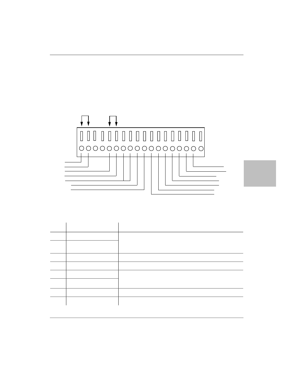
Analog Programming (APG) Connector J1
The APG connector is an 18-pin connector. See Figure 4-1.
The APG connector provides access to the following functions:
•
Sense control
•
Analog programming and monitoring.
Figure 4-1 APG Connector Terminals
Table 4-3 APG Pins and Functions J1
Pin
Reference
Function
J1.1
+SNS Positive (+)
Sense
Local Sense
}
Jumper. Factory default condition.
J1.2
+LS Positive (+)
J1.3
–NC
J1.4
–NC
J1.5
–LS Negative (–)
Local Sense
}
Jumper. Factory default condition.
Sense
J1.6
–SNS Negative (–)
J1.7
COM Analog Common
Same as power supply negative sense (–SNS)
J1.8
COM Analog Common
Same as power supply negative sense (–SNS)
1
2
3
4
5
6
7
8
9
10
11
12
13
14
15
16
17
18
Jumper
Jumper
+SNS
+LS
-LS
-SNS
COM
VOL_PR
CUR_PR
CSH
EXT_CC_CV
CUR_MON
VOL_MON
CUR_RES_PR
VOL_RES_PR
REF_I