Figure 5-1, Remote control connectors –3, Table 5-1 – Xantrex Technology XTR 850 Watt User Manual
Page 125
Hardware and Connection Setup
975-0200-01-01
5-3
5
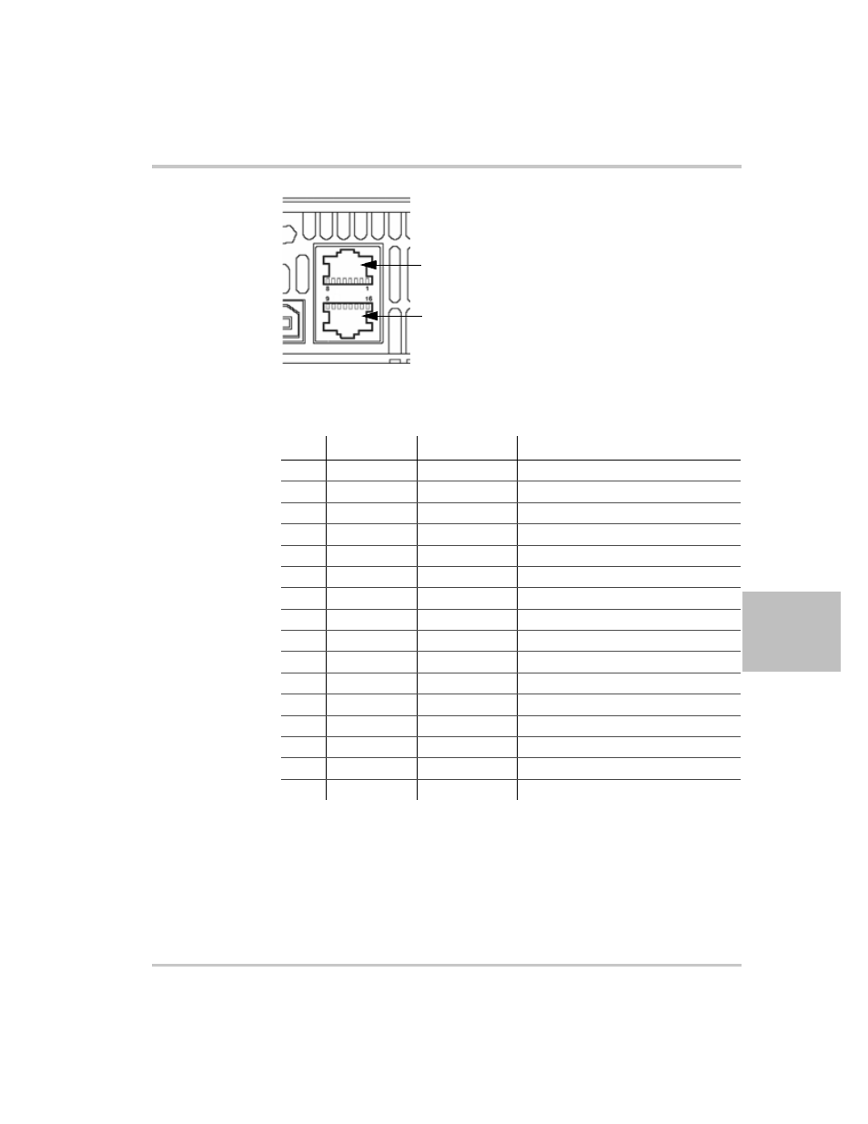
Figure 5-1 Remote Control Connectors
Table 5-1 Remote Control Connector Pins and Functions J4 and J6
1
1.All references and directions indicated in this table are with respect to
the XTR.
Pin
Reference
Direction
Function
J4.1
RX-232
Input
RS-232
J4.2
TX-232
Output
RS-232
J4.3
RXD+
Input
RS-485 receiving
J4.4
RXD–
Input
RS-485 receiving
J4.5
TXD+
Output
RS-485 transmitting
J4.6
TXD–
Output
RS-485 transmitting
J4.7
GND
–
Ground
J4.8
NC
–
–
J6.9
NC
–
–
J6.10
NC
–
–
J6.11
RXD+
Input
RS-485 receiving
J6.12
RXD–
Input
RS-485 receiving
J6.13
TXD+
Output
RS-485 transmitting
J6.14
TXD–
Output
RS-485 transmitting
J6.15
GND
–
Ground
J6.16
NC
–
–
J4:
RS-232 and RS-485
connector in port
J6:
RS-232 and RS-485
connector out port
This manual is related to the following products: