Figure 39 mstp network example – ZyXEL Communications ZyXEL Dimension GS-2024 User Manual
Page 94
Chapter 10 Spanning Tree Protocol
GS-2024 User’s Guide
94
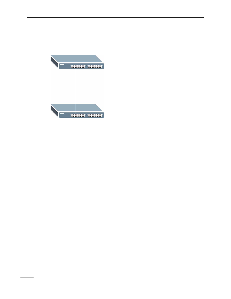
With MSTP, VLANs 1 and 2 are mapped to different spanning trees in the network. Thus
traffic from the two VLANs travel on different paths. The following figure shows the network
example using MSTP.
Figure 39 MSTP Network Example
10.1.4.2 MST Region
An MST region is a logical grouping of multiple network devices that appears as a single
device to the rest of the network. Each MSTP-enabled device can only belong to one MST
region. When BPDUs enter an MST region, external path cost (of paths outside this region) is
increased by one. Internal path cost (of paths within this region) is increased by one when
BPDUs traverse the region.
Devices that belong to the same MST region are configured to have the same MSTP
configuration identification settings. These include the following parameters:
• Name of the MST region
• Revision level as the unique number for the MST region
• VLAN-to-MST Instance mapping
10.1.4.3 MST Instance
An MST Instance (MSTI) is a spanning tree instance. VLANs can be configured to run on a
specific MSTI. Each created MSTI is identified by a unique number (known as an MST ID)
known internally to a region. Thus an MSTI does not span across MST regions.
The following figure shows an example where there are two MST regions. Regions 1 and 2
have 2 spanning tree instances.
A
B
VLAN 1
VLAN 2