1 power connector, 3 leds, Figure 13 rear panel – ZyXEL Communications ZyXEL Dimension GS-2024 User Manual
Page 41: Table 2 led descriptions
Chapter 3 Hardware Overview
GS-2024 User’s Guide
41
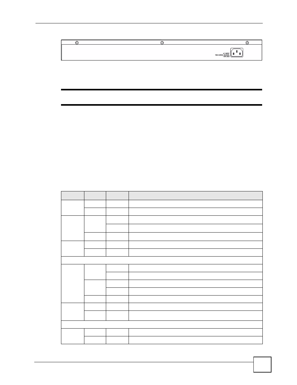
Figure 13 Rear Panel
3.2.1 Power Connector
"
Make sure you are using the correct power source as shown on the panel.
Make sure you are using the correct power source as shown on the panel.
To connect the power to the Switch, insert the female end of power cord to the power
receptacle on the rear panel. Connect the other end of the supplied power cord to a power
outlet. Make sure that no objects obstruct the airflow of the fans.
3.3 LEDs
After you connect the power to the Switch, view the LEDs to ensure proper functioning of the
Switch and as an aid in troubleshooting.
Table 2 LED Descriptions
LED
COLOR
STATUS
DESCRIPTION
PWR
Green
On
The system is turned on.
Off
The system is off.
SYS
Green
Blinking
The system is rebooting and performing self-diagnostic tests.
On
The system is on and functioning properly.
Off
The power is off or the system is not ready or is malfunctioning.
ALM
Red
On
There is a hardware failure.
Off
The system is functioning normally.
Gigabit Ports
LNK/ACT Green
Blinking
The system is transmitting/receiving to/from an Ethernet network.
On
The link to a 10/1000 Mbps Ethernet network is up.
Amber
Blinking
The system is transmitting/receiving to/from an Ethernet network.
On
The link to a 100 Mbps Ethernet network is up.
Off
The link to an Ethernet network is down.
FDX
Amber
On
The Gigabit port is negotiating in full-duplex mode.
Off
The Gigabit port is negotiating in half-duplex mode.
Mini-GBIC Slots
LNK
Green
On
The link to this port is up.
Off
The link to this port is not connected.