Location, Clock period constraints, Related resources – Xilinx MIcroblaze Development Spartan-3E 1600E User Manual
Page 23
MicroBlaze Development Kit Spartan-3E 1600 Edition User Guide
21
UG257 (v1.1) December 5, 2007
Related Resources
R
Location
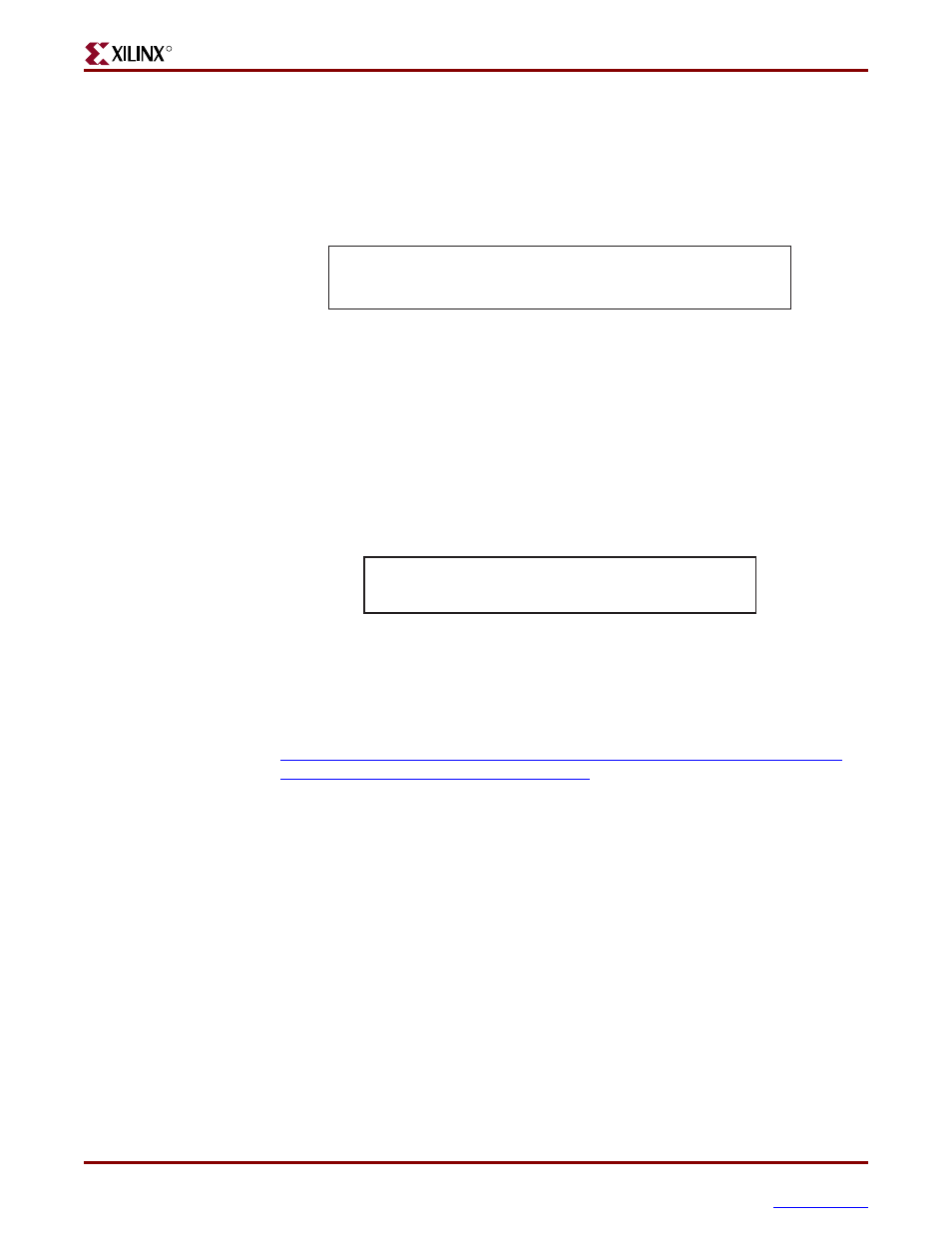
Figure 3-2
provides the UCF constraints for the three clock input sources, including the
I/O pin assignment and the I/O standard used. The settings assume that jumper JP9 is set
for 3.3V. If JP9 is set for 2.5V, adjust the IOSTANDARD settings accordingly.
Clock Period Constraints
The Xilinx ISE development software uses timing-driven logic placement and routing. Set
the clock PERIOD constraint as appropriate. An example constraint appears in
for the on-board 50 MHz clock oscillator. The CLK_50MHZ frequency is 50 MHz, which
equates to a 20 ns period. The output duty cycle from the oscillator ranges between 40% to
60%.
Related Resources
x
Epson SG-8002JF Series Oscillator Data Sheet (50 MHz Oscillator)
Figure 3-2:
UCF Location Constraints for Clock Sources
NET "CLK_50MHZ" LOC = "C9" | IOSTANDARD = LVCMOS33 ;
NET "CLK_SMA" LOC = "A10" | IOSTANDARD = LVCMOS33 ;
NET "CLK_AUX" LOC = "B8" | IOSTANDARD = LVCMOS33 ;
UG257_03_02_061306
Figure 3-3:
UCF Clock PERIOD Constraint
# Define clock period for 50 MHz oscillator
NET "CLK_50MHZ" PERIOD = 20.0ns HIGH 40%;
UG257_03_03_060206