Vanguard Managed Solutions Vanguard 6500 PLUS User Manual
Page 65
Installation
2-57
Replacing Processor Card Components
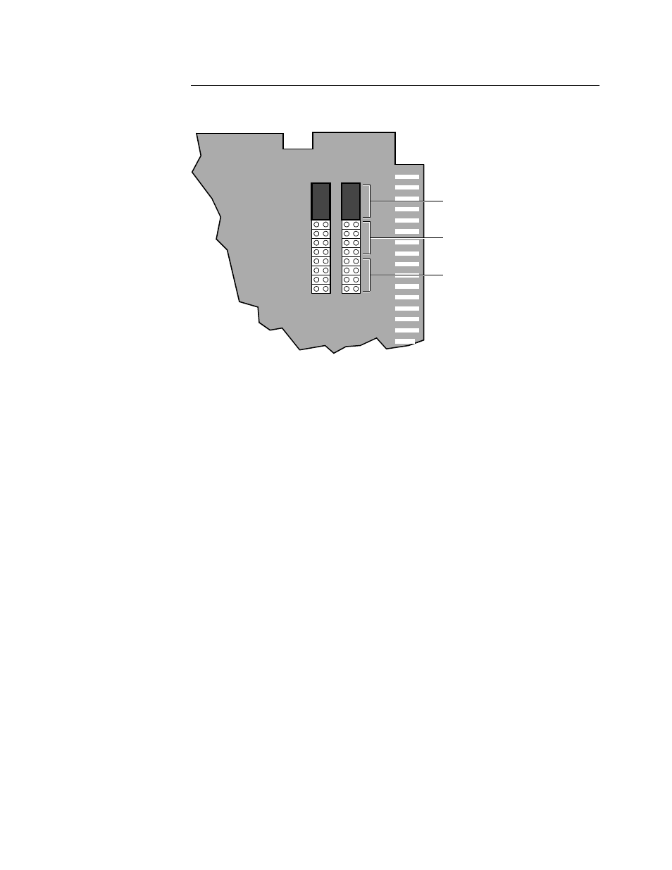
Jumpers
Figure 2-19 shows where the jumpers should be placed on the pins for various
applications and enclosures.
Figure 2-19. Jumpers on the Port Interface Pins
Po
rt
1
Po
rt
2
V.35, V.36, X.21 for
Standalone and Backplanes
with 25-Pin DB25 Connectors
V.35, V.36, X.21 for Backplanes
with 26-Pin DB26 Connectors
EIA 232 V.24