Figure 2-13), D (figure 2-13) – Vanguard Managed Solutions Vanguard 6500 PLUS User Manual
Page 55
Installation
2-47
Installing Nodes in Modulus Enclosures
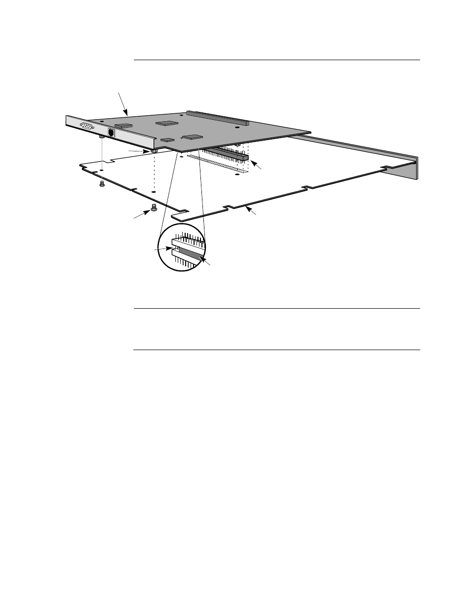
Attaching the TRIM
Card
Figure 2-13 shows the attachment of the TRIM card to the processor card.
Figure 2-13. Attaching the TRIM Card to the Processor Card
Attaching the
Cables
The LAN port is Port 55, regardless of how many active X.25, PAD, or MUX ports
are in your node. To configure the LAN port and for information about LAN
statistics, see the Vanguard ONS Basics Protocols Manual (T0106).
Trim Card
Interboard
Connector System
Header Pins
CPU Plus Board
(Solder Side)
Fastener Screw
Standoff
Ferrite
Place the 4
non-ferrite pins toward
top of processor card.
Bottom of Card
Trim Card