Vanguard Managed Solutions Vanguard 6500 PLUS User Manual
Page 29
Installation
2-21
Installing Standalone Units
Installation
Procedure
The standalone enclosure already contains a 6505
PLUS
, 6507
PLUS
, or 6525
PLUS
card.
To install the unit, follow these steps:
Rear View
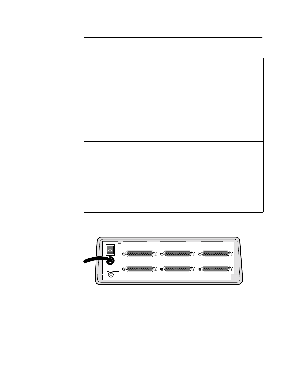
Figure 2-2 shows the rear view of the standalone enclosure.
..
Figure 2-2. Rear View of Standalone Enclosure
Step
Action
Description/Result
1
Place the unit at its designated site
and plug the power cord into a
suitable primary power source.
The power cord is attached to the
back of the unit (Figure 2-2).
2
Switch on the power, located at the
rear of the unit.
The front panel lights turn on
as described in the “Power-Up
Verification” section on
page 2-74.
After a few minutes, the green
STATUS light comes on to indicate
the node is ready to process calls.
If this does not occur, call your
VanguardMS representative.
3
Configure the unit through the
Control Terminal Port (CTP)
menus.
To access the CTP, attach a
terminal to Port 6 with an EIA
232-D connector. Port 6’s default
settings are standard terminal port
values: 9600 baud, 8 data bits, 1
stop bit, no parity.
4
When the (*) prompt appears on
the terminal, type the following:
.
ctp
At the password prompt, press
This is the default password value.
The Main menu appears. See the
Vanguard ONS Basics Protocols
Manual (T0106) for configuration
information.
PORT 6
PORT 5
PORT 4
PORT 3
PORT 2
PORT 1