1 test and diagnostic interface timing, 1 test and diagnostic interface timing, Bt8960 – Rockwell SoniCrafter BT8960 User Manual
Page 94
84
4.0 Electrical & Mechanical Specifications
4.6 Microcomputer Interface Timing
Bt8960
Single-Chip 2B1Q Transceiver
N8960DSB
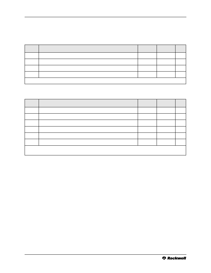
4.6.1 Test and Diagnostic Interface Timing
Table 4-15. Test and Diagnostic Interface Timing Requirements
Symbol
Parameter
Minimum
Maximum
Units
56
TCK Pulse-Width High
80
ns
57
TCK Pulse-Width Low
80
ns
58
TMS, TDI Setup prior to TCK Rising Edge
(1)
20
ns
59
TMS, TDI Hold after TCK High
(1)
20
ns
Note:
(1). Also applies to functional inputs for SAMPLE/PRELOAD and EXTEST instructions.
Table 4-16. Test and Diagnostic Interface Switching Characteristics
Symbol
Parameter
Minimum
Maximum
Units
60
TDO Hold after TCK Falling Edge
(1)
0
ns
61
TDO Delay after TCK Low
(1)
50
ns
62
TDO Enable (Low Z) after TCK Falling Edge
(1)
2
ns
63
TDO Disable (High Z) after TCK Low
(1)
25
ns
64
SMON Hold after HCLK Rising Edge
(2)
0
ns
65
SMON Delay after HCLK High
(2)
50
ns
Notes: (1). Also applies to functional outputs for the EXTEST instruction.
(2). HCLK must be programmed to operate at 16 times the symbol rate (16 x F
QCLK
).