Table 4-9, Bt8960 – Rockwell SoniCrafter BT8960 User Manual
Page 87
77
4.0 Electrical & Mechanical Specifications
4.5 Channel Unit Interface Timing
Bt8960
Single-Chip 2B1Q Transceiver
N8960DSB
Table 4-9. Channel Unit Interface Timing Requirements, Parallel Slave Mode
Symbol
Parameter
Minimum
Maximum
Units
18
TBCLK, RBCLK Period
(1)
T
QCLK
T
QCLK
19
TBCLK
,
RBCLK Pulse-Width High
T
QCLK
÷
4
20
TBCLK
,
RBCLK Pulse-Width Low
T
QCLK
÷
4
21
TQ[1,0] Setup prior to TBCLK Active Edge
(2)
25
ns
22
TQ[1,0] Hold after TBCLK High/Low
(2)
25
ns
Notes: (1). TBCLK and RBCLK must be frequency locked to QCLK though they may have independent phase relationships to QCLK
and to one another.
(2). TBCLK polarity (edge sensitivity) is programmable through the CU Interface Modes Register [cu_interface_modes
0x06].
Table 4-10. Channel Unit Interface Switching Characteristics, Parallel Slave Mode
Symbol
Parameter
Minimum
Maximum
Units
23
RQ[1,0] Hold after RBCLK Active Edge
(1)
0
ns
24
RQ[1,0] Delay after RBCLK High/Low
(1)
100
ns
Notes: (1). RBCLK polarity (edge sensitivity) is programmable through the CU Interface Modes Register [cu_interface_modes;
0x06].
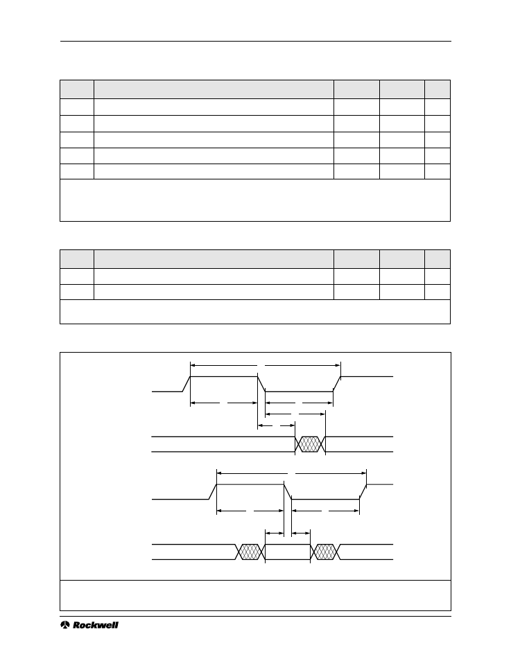
Figure 4-4. Channel Unit Interface Timing, Parallel Slave Mode
Note:
TBCLK and RBCLK polarities are programmable through the CU Interface Modes register. The figure depicts both clocks
programmed to falling-edge active.
RQ[1:0]
TBCLK
TQ[1:0]
RBCLK
18
19
20
21
22
23
24
18
19
20