Raymarine GPS navigation User Manual
Page 11
2.3.1 Power Input
The
NAV
is intended for use on vessels with 12 VDC power systems
and can operate as long as the DC supply is maintained between 10 and 16
volts. The DC power system can be “negative” ground or have both positive
and negative supply lines “floating” above ground. The
NAV 398 is
not
A 6 foot cable assembly containing wiring for the DC power and Data
Output is supplied with your display unit and in many cases will be adequate
to reach near the source of the 12 VDC power.
For best noise immunity
from other shipboard elec-
tronics, if possible, avoid
grouping the power connec-
tions on the same circuit
breaker with radar, radio, or
echo sounder power leads.
The NAV unit’s wiring
should be kept separate as
much as possible from other
devices.
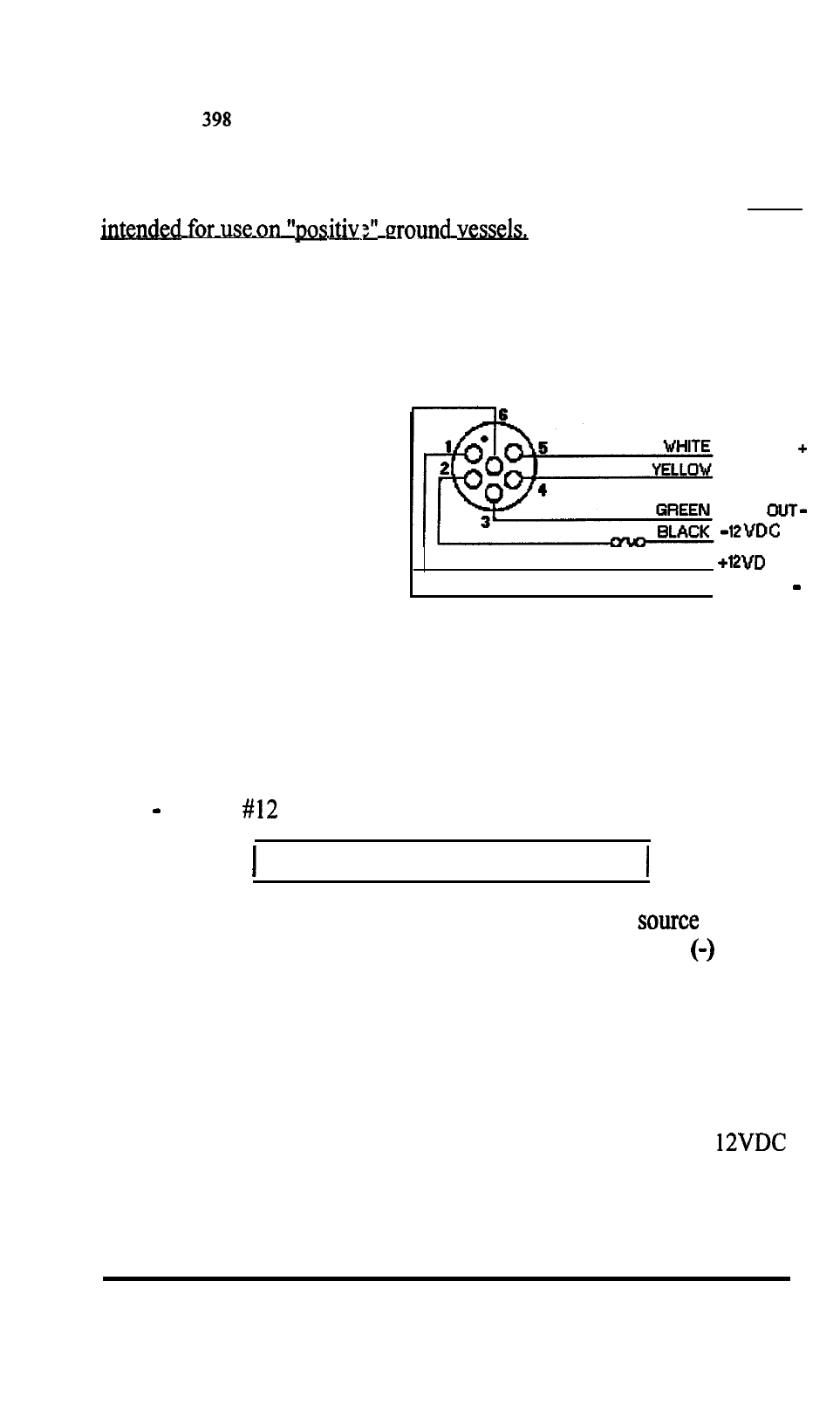
FUSE
RED
BROWN
DATA IN
DATA OUT+
DATA
C
DATA IN
Power Cable Wiring Diagram
Although the
NAV
unit’s power consumption is typically less than 5 watts,
if the power leads need to be extended more than 10 feet, the wire size of the
leads should be increased accordingly to minimize line losses. For cable runs
of 20 35 feet
AWG wire is recommended.
OBSERVE PROPER POLARITY!
The RED wire should be connected to the POSITIVE (+)
terminal;
the BLACK wire should be connected to the NEGATIVE
source
terminal If the power leads are accidentally reversed, the in-line fuse will
blow. If this happens, recheck the polarity of the connections with a voltmeter
(VOM) and, if necessary, reverse the leads for proper connection. Replace
the fuse.
2.3.2 Sensor Connections
The sensor units used with the
NAV
398
normally obtain their
operating power input from the
NAV
unit and, when the
NAV
unit has been
turned ON, the sensors can then proceed to locate and track signals and
INSTALLATION 2-5