Installation, Venting arrangements, Inst alla tion – Regency P40 User Manual
Page 14
Regency
®
P40-1 Direct Vent Gas Fireplace
14
INST
ALLA
TION
INSTALLATION
VENTING ARRANGEMENTS
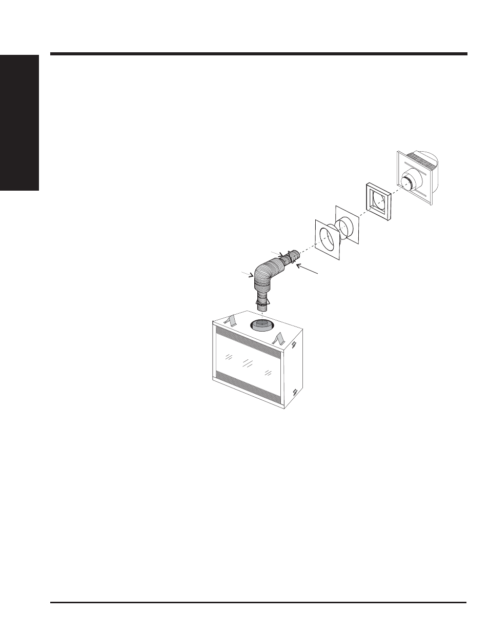
HORIZONTAL TERMINATION (FLEX)
Regency
®
Direct Vent System
These venting systems, in combination with the P40 Direct Vent Gas Fireplace, have been tested and listed as a direct vent heater system by
Warnock Hersey. The location of the termination cap must conform to the requirements in the Vent Terminal Locations diagram in "Exterior Vent
Termination Requirements" section.
Regency
®
Direct Vent (Flex) System
Termination Kit (Part# 946-618) includes all
the parts needed to install the P40 with a
maximum run of 6 feet.
1) 8" dia. fl exible liner (6 ft. length)
2) 5" dia. fl exible liner (6 ft. length)
3) spring spacers (4)
4) thimble
5) AstroCap XL termination cap (1)
6) screws (12)
7) tube of Mill Pac (1)
8) plated screws (8)
9) screws #8 x 1-1/2" Drill Point,
Stainless Steel (4)
10) vinyl siding standoff
If longer runs are needed, the Regency
®
Direct
Vent system (Flex) Part# 946-616 includes
all the parts needed to install the P40 with a
maximum 10' run.
1) 8" dia. fl exible liner (10 ft. length)
2) 5" dia. fl exible liner (10 ft. length)
3) spring spacers (7)
4) thimble (2)
5) AstroCap XL termination cap (1)
6) screws (12)
7) tube of Mill Pac (1)
8) plated screws (8)
9) screws #8 x 1-1/2" Drill Point,
Stainless Steel (4)
10) vinyl siding standoff
Notes:
1) Liner sections should be continuous without any joints or seams.
2) Only Flex pipe purchased from FPI may be used for Flex installations.
3) Horizontal vent must be supported every 3 feet. (For 10' fl ex kit 946-616 only.)
8" dia.
Flue pipe
5” dia. flue pipe
spring spacer
(Part# 946-623/P)
AstroCap XL
Wall Thimble
(required in Canada only)
Vinyl Siding
Standoff