Hardware reference, Drive functional specification, Drive functional – Parker Products ViX250AE User Manual
Page 120
8. HARDWARE REFERENCE
113
8. Hardware Reference
Drive Functional
Specification – ViX250AE, ViX500AE
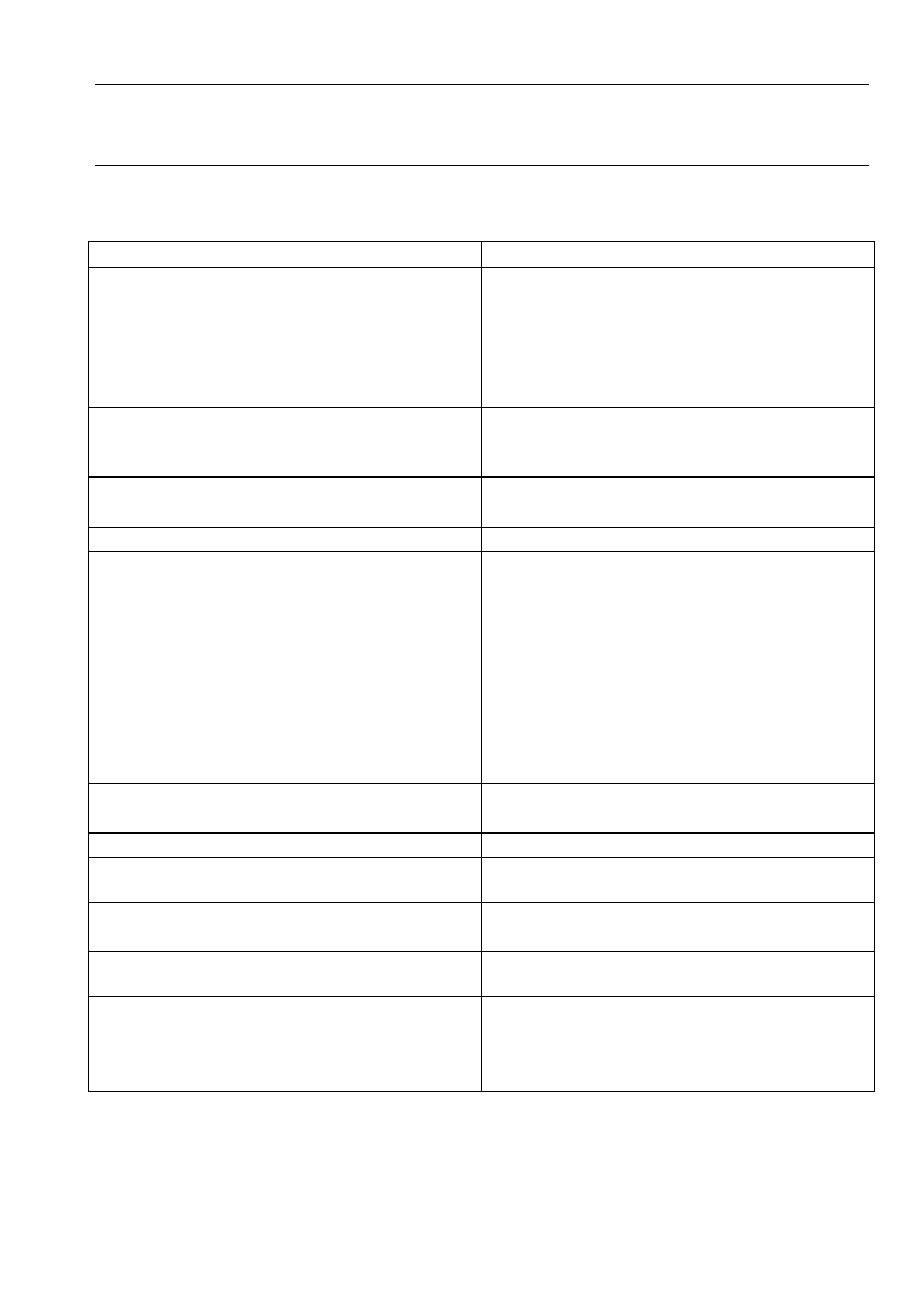
Parameter
Value
Maximum output current
Maximum continuous power drawn from the
supply
ViX500: 5A RMS continuous
15A RMS peak (2 seconds max.)*
ViX250: 2.5A RMS continuous
7.5A RMS peak (2 seconds max.)*
6.3A at 80V (500VA)
Motor HV supply input
(No reverse polarity protection, HV
reversal WILL damage the drive)
ViX500: 48 – 80V DC +5% -15%
ViX250: 24 – 80V DC +5% -15%
Minimum PSU capacitance
ViX500: 6,600
µ
F
ViX250: 3,300
µ
F
Controller supply input
24V DC +10% to –15%
Protection
Short circuit (phase-to-phase, phase-to-
ground)
Motor HV over and under voltage trip
(HV over voltage 98V nominal)
Drive over-temperature
Motor over-temperature (motor dependent)
24V reverse polarity
Commutation encoder fault
Resolver fault
Temperature protection (motor protection
depends upon the type used) see Note 1.
I
2
t circuit protects motor and drive from
excessive dissipation
Motor current limit
Selectable by software
Motor inductance range
0.5 to 10 mH For lower inductance motors
consult Digiplan
Fault output
NPN open-collector output, normally low,
active high
Enable input
24V input with pull-up resistor (can be
software set to be active high or active low)
LED status indicators (tri-colour)
HV/feedback fault
Drive fault
Comms. status
* 2 sec rotating 0.4 sec stationary – see Plots of I
2
t Against Drive Current
Table 8-1. Functional Specification
Note 1 – See Motor Overtemperature Sensor in Electrical Installation section.