Konica Minolta C250P User Manual
Page 50
Installation and operation precautions
1
C250P
1-31
* Parts marked with an asterisk (*) are installed within the finisher and therefore are not shown in
the illustration.
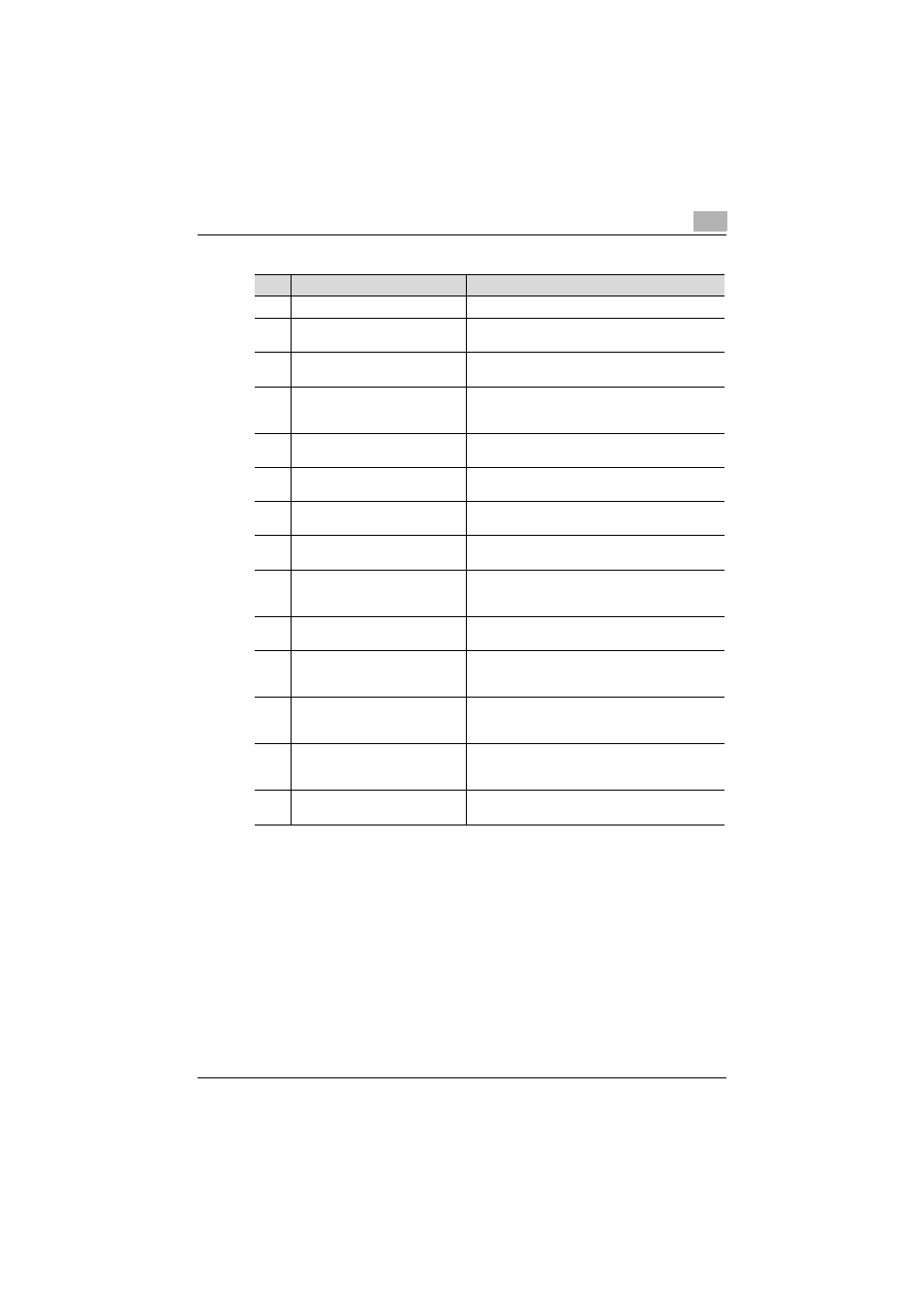
No.
Part Name
Description
1
Exit tray 1
Collects printed pages
2
Upper door
Opened when clearing paper misfeeds (See
p. 8-31.)
3
Horizontal transport unit cover
Opened when clearing paper misfeeds from the
horizontal transport unit (See p. 8-31.)
4
Hole-punch waste container
Removed when emptying hole-punch waste that
has accumulated from using the Punch settings
(See p. 7-6.)
5
Misfeed-clearing guide
Opened when clearing paper misfeeds within the
finisher (See p. 8-31.)
6
Right-side door
Opened when clearing paper misfeeds within the
finisher (See p. 8-31.)
7
Exit tray 2
Collects copies printed using the “Fold & Staple”
setting
8
Misfeed-clearing dial in folding
section
Turned when clearing paper misfeeds in the folding
section (See p. 8-31.)
9
Staple cartridge holder
Removed from the stapler unit when clearing
jammed staples or replacing the staple cartridge
(See p. 6-13, p. 8-46.)
10
Misfeed-clearing dial 1
Turned when clearing paper misfeeds within the
finisher (See p. 8-31.)
11
Misfeed-clearing dial 2
Turned when clearing jammed staples or replacing
the staple cartridge, or for moving the staple
cartridge holder out to the front (See p. 8-46.)
12
Stapler unit
Pulled out when clearing jammed staples or
replacing the staple cartridge (See p. 6-13,
p. 8-46.)
13
Front door
Opened when clearing paper misfeeds or jammed
staples or when replacing the staple cartridge (See
p. 6-13, p. 8-46.)
14
Punch kit*
Punches holes for filing printed pages when punch
kit is installed onto Finisher