6 pc3: reader position sensor, 7 pc4: scan position sensor, 8 pu1: power unit – Kodak 2400DSV User Manual
Page 122: 9 pu2: projection lamp regulator, 10 s1: power switch
Troubleshooting
7
115
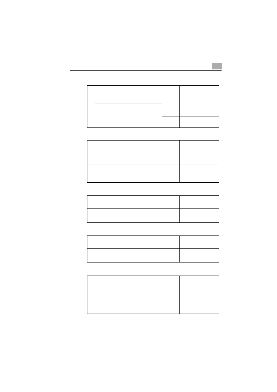
7.6.6
PC3: Reader Position Sensor
7.6.7
PC4: Scan Position Sensor
7.6.8
PU1: Power Unit
7.6.9
PU2: Projection Lamp Regulator
7.6.10 S1: Power Switch
1
Is the voltage across PJ8-B12 on PWB-BB
and GND 0V when the Power ON/OFF
Switch is in the ON position and the light
emitted by the Sensor LED is blocked?
→No
Replace PC3.
↓ Yes
2
Is the voltage across PJ8-B12 on PWB-BB
and GND DC5V when the light emitted by the
Sensor LED strikes the Sensor
photosensitive element?
→No
Replace PC3.
→Yes
OK
1
Is the voltage across PJ8-A6 on PWB-BB
and GND 0V when the Power ON/OFF
Switch is in the ON position and the light
emitted by the Sensor LED is blocked?
→No
Replace PC4.
↓ Yes
2
Is the voltage across PJ8-A6 on PWB-BB
and GND DC5V when the light emitted by the
Sensor LED strikes the Sensor
photosensitive element?
→No
Replace PC4.
→Yes
OK
1
Is the Fuse of PU1 blown?
→Yes
Replace Fuse.
↓ No
2
Is the output voltage of each Connector
correct when the Power Switch is in the ON
position?
→No
Replace PU1.
→Yes
OK
1
Is the Fuse of PU2 blown?
→Yes
Replace Fuse.
↓ No
2
Is the voltage across CN7-1 and CN7-2
DC17.0V when the machine is in the reader
mode?
→No
Replace PU2.
→Yes
OK
1
Are the circuits across 1 and 2, and 3 and 4
conducting when the Power Switch is
removed from the machine and in the OFF
position?
→Yes
Replace S1.
↓ No
2
Are the circuits across 1 and 2, and 3 and 4
conducting when the Switch is in the
position?
→No
Replace S1.
→Yes
OK