6 electrical components check, 1 la1: projection lamp, 2 m3: power unit cooling fan motor – Kodak 2400DSV User Manual
Page 121: 3 m4: projection lamp cooling fan motor, 4 pc1: image leading edge sensor, 5 pc2: scan mirror position sensor
7
Troubleshooting
114
7.6
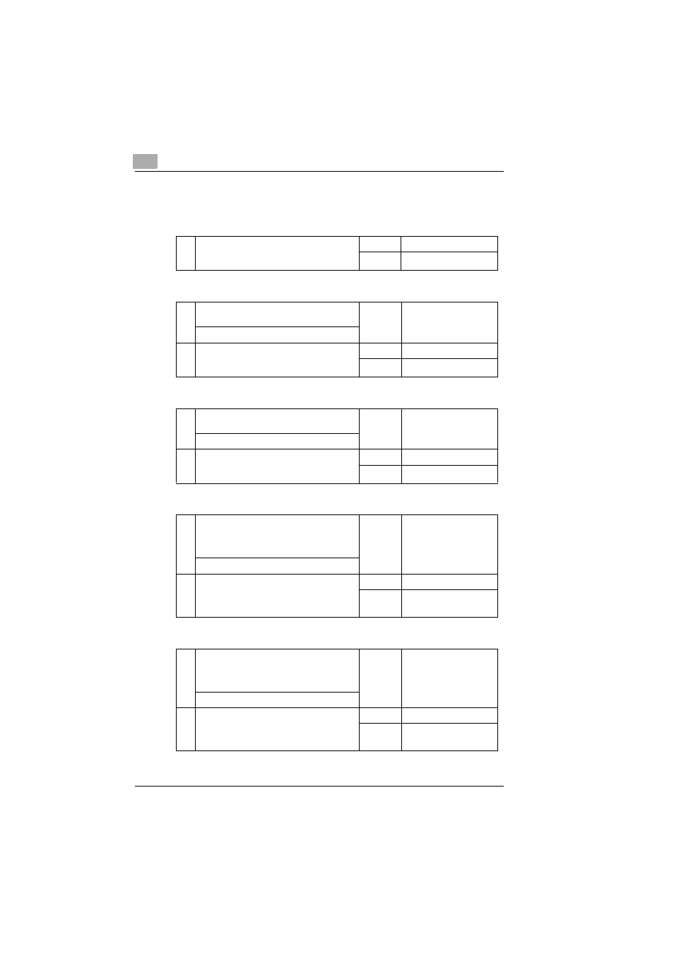
Electrical Components Check
7.6.1
LA1: Projection Lamp
7.6.2
M3: Power Unit Cooling Fan Motor
7.6.3
M4: Projection Lamp Cooling Fan Motor
7.6.4
PC1: Image Leading Edge Sensor
7.6.5
PC2: Scan Mirror Position Sensor
1
Is the circuit across both terminals of the
Lamp conducting when the Lamp is removed
from the machine?
→No
Replace LA1.
→Yes
OK
1
Does the Motor start rotating when the Power
ON/OFF Switch is turned ON?
→Yes
OK
↓ No
2
Is the voltage across CN10-1 and GND
DC24V with the Power Switch in the ON
position?
→No
Check wiring.
→Yes
Replace M3.
1
Does the Motor start rotating when the Power
ON/OFF Switch is turned ON?
→Yes
OK
↓ No
2
Is the voltage across CN18-1 and GND
DC24V with the Power ON/OFF Switch in the
ON position?
→No
Check wiring.
→Yes
Replace M4.
1
Is the voltage across PJ8-A3 on PWB-BB
and GND 0V when the Power Switch is in the
ON position and the light emitted by the
Sensor LED is blocked?
→No
Replace PC1.
↓ Yes
2
Is the voltage across PJ8-A3 on PWB-BB
and GND DC5V when the light emitted by the
Sensor LED strikes the Sensor
photosensitive element?
→No
Replace PC1.
→Yes
OK
1
Is the voltage across PJ8-B15 on PWB-BB
and GND 0V when the Power Switch is in the
ON position and the light emitted by the
Sensor LED is blocked?
→No
Replace PC2.
↓ Yes
2
Is the voltage across PJ8-B15 on PWB-BB
and GND DC5V when the light emitted by the
Sensor LED strikes the Sensor
photosensitive element?
→No
Replace PC2.
→Yes
OK