Figure 814. j1850 receiver (j_rx) register, Figure 815. j1850 receive message structure, 2 receiving messages – Intel 8XC196Lx User Manual
Page 81: Receiving messages -15, J1850 receive message structure -15, J1850 receiver (j_rx) register -15
8-15
J1850 COMMUNICATIONS CONTROLLER
NOTE
An overrun condition can occur on transmission if the transmit buffer,
JTX_BUF, is overwritten.
8.5.2
Receiving Messages
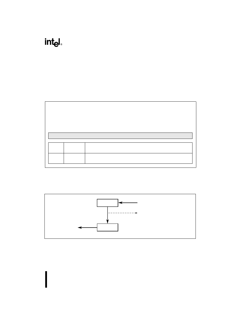
For a message reception, after a SOF is detected on the bus, the controller starts to shift data sym-
bols into the J1850 receive buffer (JRX_BUF) until an entire data byte has been received. This
byte is automatically transferred into the J1850 receive (J_RX) register (Figure 8-14) and the sub-
sequent byte is written into the empty JRX_BUF.
The transfer of the first byte to J_RX triggers the reception process and generates the J1850 re-
ception (J1850RX) interrupt (if it is enabled), signaling that JRX_BUF is available for another
byte (Figure 8-15).
Figure 8-15. J1850 Receive Message Structure
After J_RX is read, the byte residing in JRX_BUF is automatically shifted into J_RX, freeing
JRX_BUF for another reception. This process continues until an end of data (EOD) symbol is en-
countered.
J_RX
Address:
Reset State:
1F52H
00H
The J1850 receiver (J_RX) register transfers received data in byte increments from the J1850 bus to
the microcontroller CPU. This register is buffered to allow for reception of a second data byte while
the first data byte is being read. This byte register can be read or written, and is addressable through
windowing.
7
0
Receive Byte
Bit
Number
Bit
Mnemonic
Function
7:0
DB7:0
Data Bits
These eight bits compose the last data byte received from the J1850 bus.
Figure 8-14. J1850 Receiver (J_RX) Register
A5236-01
CPU
J_RX
JRX_BUF
Message receive
interrupt (J1850RX) set
J1850 Bus