Figure a3. 83c196ld 52-pin plcc package, Table a4. definition of status symbols, A.2 default conditions – Intel 8XC196Lx User Manual
Page 115: And v, Table a-4. definition of status symbols
A-7
SIGNAL DESCRIPTIONS
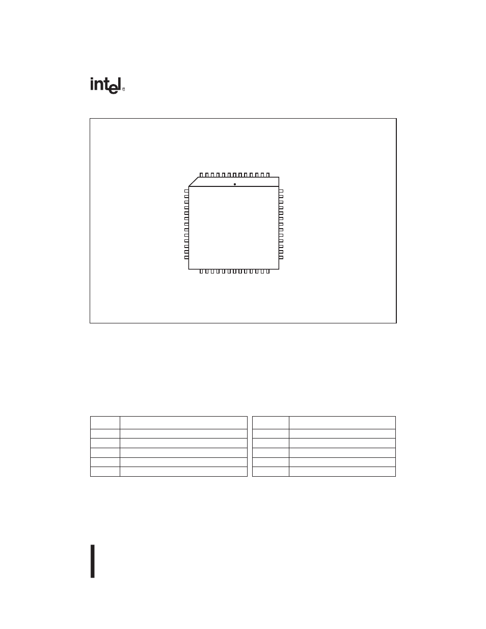
Figure A-3. 83C196LD 52-pin PLCC Package
A.2 DEFAULT CONDITIONS
Table A-5 lists the values of the signals for the 87C196LA and 87C196LB during various oper-
ating conditions. Table A-6 lists the same information for the 83C196LD. Table A-4 defines the
symbols used to represent the pin status. Refer to the DC characteristics table in the datasheet for
actual specifications for V
OL
, V
IL
, V
OH
, and V
IH
.
Table A-4. Definition of Status Symbols
Symbol
Definition
Symbol
Definition
0
Voltage less than or equal to V
OL
, V
IL
MD0
Medium pull-down
1
Voltage greater than or equal to V
OH
, V
IH
MD1
Medium pull-up
HiZ
High impedance
WK0
Weak pull-down
LoZ0
Low impedance; strongly driven low
WK1
Weak pull-up
LoZ1
Low impedance; strongly driven high
ODIO
Open-drain I/O
A3403-02
P6.1 / EPA9
P6.0 / EPA8
P1.0 / EPA0 / T2CLK
P1.1 / EPA1
P1.2 / EPA2 / T2DIR
P1.3 / EPA3
V
CC
V
SS
P0.7
P0.6
P0.5
P0.4
P0.3
7.
4
P /
5
1
D
A
#L
R
W /
#
R
W /
2.
5
P
#
D
R /
3.
5
P V
P
P
V
S
S
EL
A /
#
V
D
A /
0.
5
P V
S
S
1L
AT
X
2L
AT
X
1
D
S /
7.
6
P
1
C
S /
6.
6
P
0
D
S /
5.
6
P
0
C
S /
4.
6
P
AD14 / P4.6
AD13 / P4.5
AD12 / P4.4
AD11 / P4.3
AD10 / P4.2
AD9 / P4.1
AD8 / P4.0
AD7 / P3.7
AD6 / P3.6
AD5 / P3.5
AD4 / P3.4
AD3 / P3.3
AD2 / P3.2
46
45
44
43
42
41
40
39
38
37
36
35
34
xx83C196LD
View of component as
mounted on PC board
8
9
10
11
12
13
14
15
16
17
18
19
20
1.
3
P /
1
D
A
0.
3
P /
0
D
A
#T
E
S
E
R
#
A
E V
S
S
V
C
C
D
XT
/
0.
2
P
D
X
R /
1.
2
P
T
NI
T
X
E /
2.
2
P
4.
2
P
#
E
C
N
O /
6.
2
P
T
U
O
KL
C /
7.
2
P
2.
0
P
12 22 32 42 52 62 72 82 92 03 13 23 33
7 6 5 4 3 2 1 25 15 05 94 84 74