Figure 111. slave programming circuit, Table 113. slave programming mode address map, Slave programming circuit -3 – Intel 8XC196Lx User Manual
Page 103: Slave programming mode address map -3
11-3
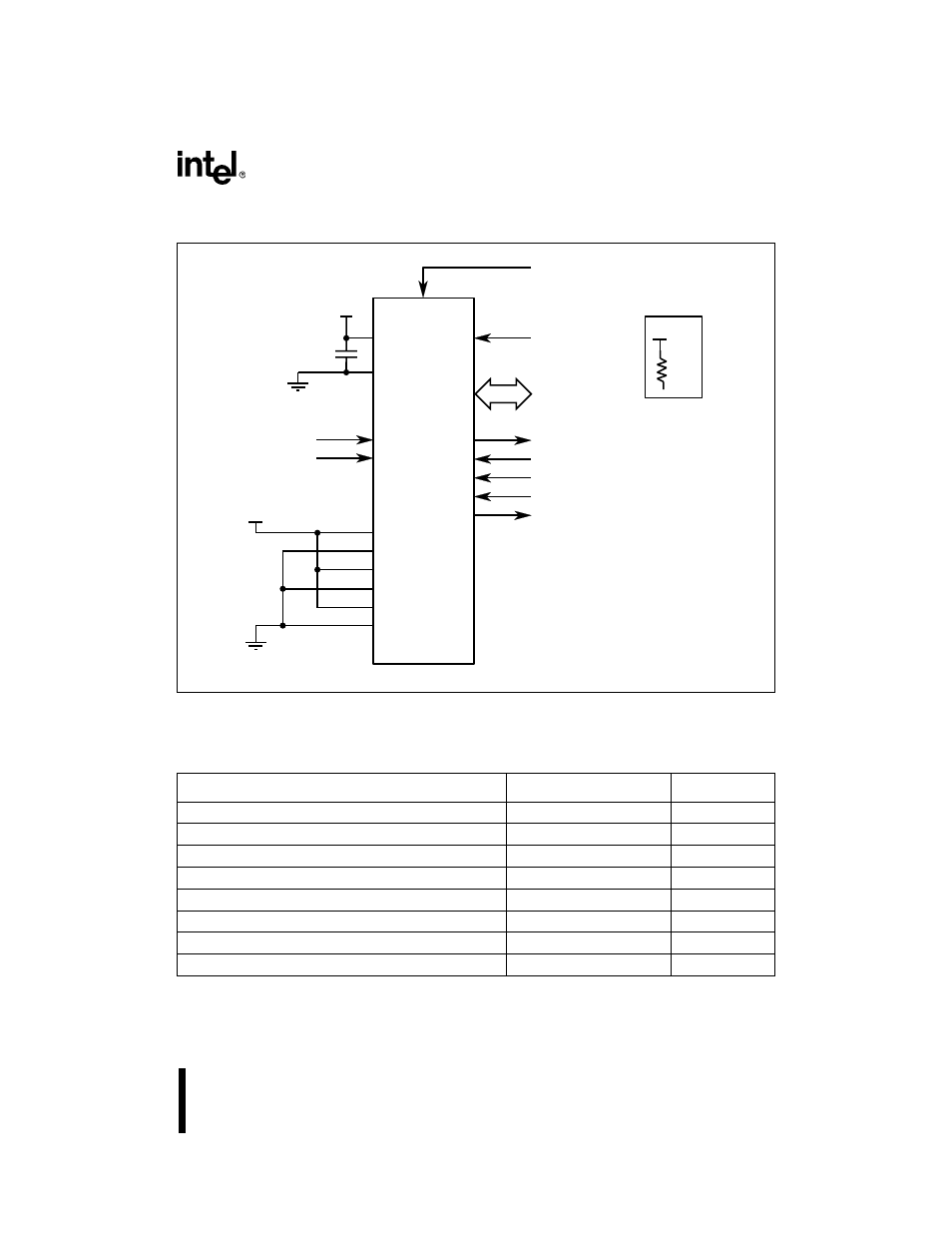
PROGRAMMING THE NONVOLATILE MEMORY
Figure 11-1. Slave Programming Circuit
Table 11-3. Slave Programming Mode Address Map
Description
Address
Comments
OTPROM
2000–7FFFH
OTPROM Cells
OFD
0778H
OTPROM Cell
DED
†
0758H
UPROM Cell
DEI
†
0718H
UPROM Cell
PCCB
0218H
Test EPROM
Programming V
CC
0072H
Read Only
Programming V
PP
0073H
Read Only
Signature word
0070H
Read Only
†
These bits program the UPROM cells. Once these bits are programmed, they cannot be erased, and
dynamic failure analysis of the device is impossible.
P2.6
P2.4
P2.2
P2.1
P2.0
P0.7/PMODE.3
P0.6/PMODE.2
P0.5/PMODE.1
P0.4/PMODE.0
ANGND
EA#
XTAL1
0.1 µF
RESET#
CLOCK
EA#
Pullups Required
P4.7 - P3.0
87C196LA, LB
RESET#
10
k
Ω
V
CC
V
CC
V
PP
V
CC
A5277-01
V
REF
V
CC
V
SS
P3.7:0
P4.7:0
PBUS
V
PP
CPVER
AINC#
PROG#
PALE#
PVER