Older cable box, Vcr to a cable box (audio & video), Tv connections – MITSUBISHI ELECTRIC WD-65736 User Manual
Page 22: Out on the cable box to ant 1 on the tv back panel, Bcmfcpy 57cbdlqbofm, 7$3 57cbdl qbofm, Ant 1 / main
22
3. TV Connections
Older Cable Box
Required: One coaxial cable.
Note: This connection is not recommended. The
other connections described in this chapter
provide better quality audio and video to the TV
and allow NetCommand to work with the cable
box.
Connect the incoming cable to
1.
IN on cable box.
Connect one coaxial cable from
2.
OUT on the cable
box to ANT 1 on the TV back panel.
HDMI
3D
GLASSES
EMITTER
AVR
AUDIO
OUTPUT
DIGITAL
AUDIO
OUTPUT
L
R
L
R
(480i / 480p / 720p / 1080i)
L
R
DVI/PC
INPUT
VIDEO
Y
Pb
Pr
AUDIO
Pb
Y/ VIDEO
Pr
VIDEO: 480i/480p/720p/1080i/1080p
AUDIO: PCM STEREO
PC: VGA, W-VGA, SVGA, W-SVGA,
XGA, W-ZGA, SXGA, 720p/ 1080p
1
2
3
HDMI
IR-
NetCommand
Output / External
Controller Input
R
INPUT
3
INPUT
2
INPUT
1
S-VIDEO
INPUT 3
AUDIO
R
L
AUDIO
ANT 2 / AUX
ANT 1 / MAIN
HDMI
3D
GLASSES
EMITTER
AVR
AUDIO
A
OUTPUT
O
DIGITAL
AUDIO
OUTPUT
L
R
L
R
(480i / 480p / 720p / 1080i)
L
R
DVI/PC
INPUT
VIDEO
Y
Pb
Pr
AUDIO
Pb
Y/ VIDEO
Pr
VIDEO: 480i/480p/720p/1080i/1080p
AUDIO: PCM STEREO
PC: VGA, W-VGA, SVGA, W-SVGA,
XGA, W-ZGA, SXGA, 720p/ 1080p
1
2
3
HDMI
IR-
NetCommand
Output / External
Controller Input
R
INPUT
3
INPUT
2
INPUT
1
S-VIDEO
INPUT 3
AUDIO
R
L
AUDIO
ANT 2 / AUX
ANT 1 / MAIN
ANT 1 / MAIN
ANT 1 / MAIN
*/
065
$BCMFCPY
57CBDLQBOFM
*ODPNJOH
DBCMF
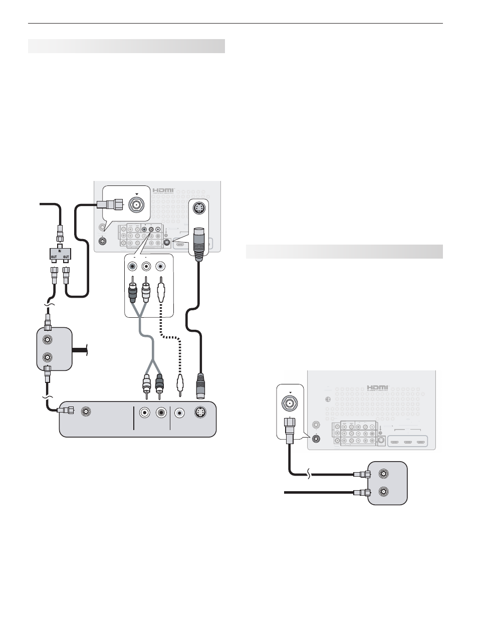
Figure 10. Connecting an older cable box
VCR to a Cable Box (Audio & Video)
Required: Two-way RF splitter, three coaxial cables,
right and left audio cables, S-Video or composite video
cable, plus video and audio cables required to connect
the TV to the cable box.
Connect the incoming cable to
1.
IN on the RF splitter.
Connect one coaxial cable from
2.
OUT on the RF
splitter to CABLE IN on the cable box.
Connect one coaxial cable from
3.
OUT on the RF
splitter to ANT 1 on the TV back panel.
Connect one coaxial cable from
4.
OUT on the cable
box to ANTENNA IN on the VCR back panel.
HDMI
3D
GLASSES
EMITTER
AVR
AUDIO
OUTPUT
DIGITAL
AUDIO
OUTPUT
L
R
L
R
(480i / 480p / 720p / 1080i)
L
R
DVI/PC
INPUT
VIDEO
Y
Pb
Pr
AUDIO
Pb
Y/ VIDEO
Pr
VIDEO: 480i/480p/720p/1080i/1080p
AUDIO: PCM STEREO
PC: VGA, W-VGA, SVGA, W-SVGA,
XGA, W-ZGA, SXGA, 720p/ 1080p
1
2
3
HDMI
IR-
NetCommand
Output / External
Controller Input
R
INPUT
3
INPUT
2
INPUT
1
S-VIDEO
INPUT 3
AUDIO
R
L
AUDIO
ANT 2 / AUX
ANT 1 / MAIN
HDMI
3D
GLASSES
EMITTER
AVR
AUDIO
A
OUTPUT
O
DIGITAL
AUDIO
OUTPUT
L
R
L
R
(480i / 480p / 720p / 1080i)
L
R
DVI/PC
INPUT
VIDEO
Y
Pb
Pr
AUDIO
Pb
Y/ VIDEO
Pr
VIDEO: 480i/480p/720p/1080i/1080p
AUDIO: PCM STEREO
PC: VGA, W-VGA, SVGA, W-SVGA,
XGA, W-ZGA, SXGA, 720p/ 1080p
1
2
3
HDMI
IR-
NetCommand
Output / External
Controller Input
R
R
INPUT
3
INPUT
2
INPUT
1
S-VIDEO
INPUT 3
AUDIO
R
L
AUDIO
ANT 2 / AUX
ANT 1 / MAIN
S-VIDEO
INPUT 3
AUDIO
R
L
AUDIO
R
L
S-VIDEO
INPUT 3
VIDEO
VIDEO
ANT 1 / MAIN
ANT 1 / MAIN
"6%*0065
47*%&0
065
7*%&0
065
-
3
"/5&//"
*/
*/
065
7$3
57CBDL
QBOFM
*ODPNJOH
DBCMF
$BCMFCPY
"VEJPBOE
WJEFPGSPN
DBCMFCPY
UP57
Figure 9. Connecting a VCR to a cable box
Connect the cable box outputs to the TV as shown
5.
in one of the options listed below. This connection
allows the TV to receive the best available signal
directly from the cable box.
t
'JHVSF QBHF Component video output to
the TV’s Y Pb Pr jacks; analog stereo audio to
the associated AUDIO jacks.
t
Figure 2, page 19: HDMI output to the TV’s
HDMI jack.
t
Figure 7, page 21: S-Video output to the TV’s
INPUT 3 S-VIDEO jack; analog stereo audio to
the INPUT 3 AUDIO jacks.
Connect either an S-Video or composite video
6.
cable from VIDEO OUT on the VCR back panel
to a VIDEO composite or S-VIDEO jack on the TV
back panel. Connect only one type of video cable.
S-Video is preferable to composite video, if avail-
able.
To use the TV speakers with the VCR, connect left
7.
(white) and right (red) audio cables from AUDIO OUT
on the VCR back panel to the associated INPUT
AUDIO L and R on the TV back panel. If your VCR
is mono (non-stereo), connect only the white (left)
cable.
Note: When using this connection configuration with the
connections used in step 5, it is possible to view
live cable programs through the VCR Device. For
best picture quality always view live cable programs
directly from the TV input connected to the cable
box device.