GarrettCom 6K8 User Manual
Page 45
Magnum 6K8-Series Industrial Field Switch Installation and User Guide (04/07)
40
www GarrettCom com
.
.
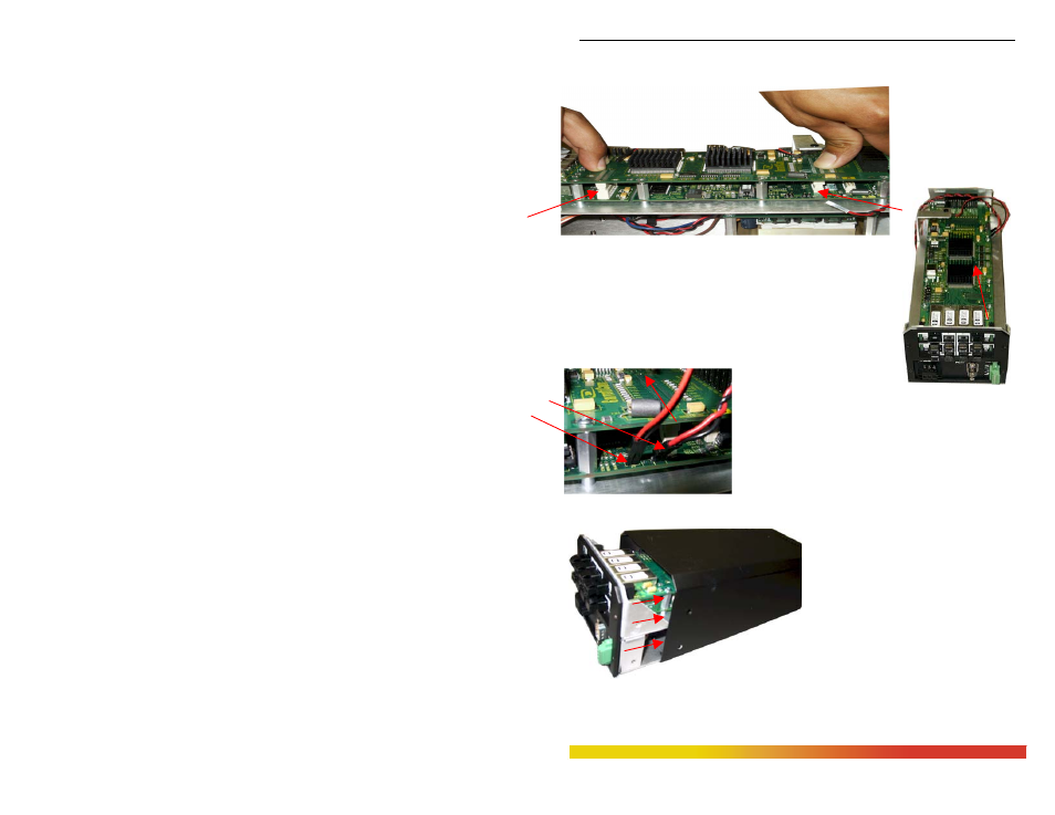
press slowly and firmly with two fingers (as shown below in Fig. 3.6.2f) on the
top of the latching connectors until the connectors latched up securely.
Figure 3.6.2f:
Securely latching up
6KPMV Cards into a
Magnum 6K8-Series
Step 6. Now screw
down the daughter board with 6 #440 screws, so that it
holds the daughter board securely. The figure on the
left shows the top view of successfully installed
6KPMV cards inside and the Power Led (pin J5) and
Power supply cable (pin DSSV) connected to the
board pins as shown in Fig 3.6.2g with arrows.
Fig. 3.6.2g Top View:
6KPM Module installed and
insight for connecting two wires to the right pins
Step 7. Once the installation of granddaughter and
daughter modules is done, the front panel screen plates
of 6KPMV need to be placed on the face of the module
securely and carefully. Now screw down properly the
faceplate with 4 screws to complete the installation
process for port module. The front panel screen plate does not need any screws
to hold on port module, but need
to place tightly and carefully
while placing on LEDs.
Fig. 3.6.2h sliding in the top cover
onto the chassis base track
Step 8. Once 6KPMV card have been
installed (including faceplate
and screen plate), the chassis
cover should be replaced. Make
sure the chassis top cover is aligned properly to the base before securely sliding
the chassis base track inside the top cover properly as shown in Fig. 3.6.2h.