GarrettCom 6K8 User Manual
Page 42
Magnum 6K8-Series Industrial Field Switch Installation and User Guide (04/07)
37
www GarrettCom com
.
.
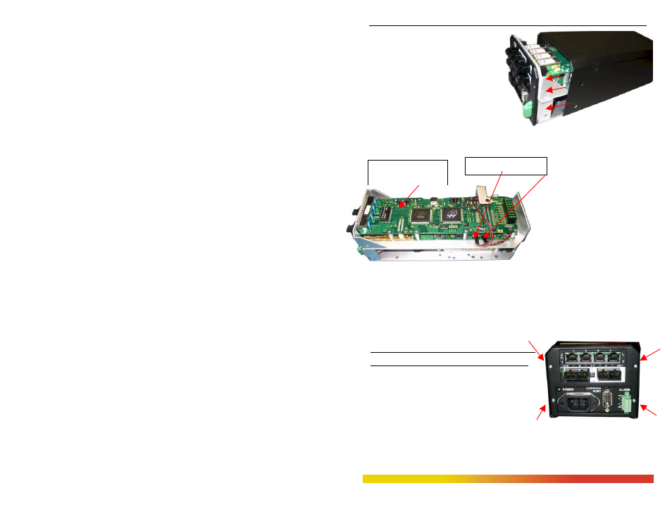
Step 2. Remove Chassis Cover
The Magnum 6K8-
Series chassis consists of top cover and
bottom chassis assembled together with
the help of 12 Philips-head screws. There
are 4 screws located on the topside panel
of the unit (2 each on both side), 8 for
bottom chassis base of the unit. Remove
these screws. Once these screws are
removed, the top-cover is easily slide out
to the front, off the chassis base, as shown in the picture above in Fig. 3.6.1a.
Figure 3.6.1a: Removing the Top panel from the Chassis base of the unit
Caution: Be
careful not to
disturb the
power supply.
When the chassis
top cover has been removed,
the interior of the unit is
exposed. Looking down into
the Magnum 6K8-Series unit, notice that there are PM module installed and daughter
module would be facing your eyes on the top installed on the main board with J5 and
DSSV pins connected on the right. (See Figure 3.6.1b below).
Figure 3.6.1b: Magnum 6K8-Series, Top view without chassis cover w/ daughter
module on the top.
Note: Un-hooked the J5and DSSV connected wires
first as shown in Figure above with arrow mark.
Step 3. Remove front panel faceplate retaining
screws and screen plate
There are four retaining screws as shown with arrow
mark in Fig 3.6.1c holding the faceplate of the
chassis. Figure 3.6.1c: Top View – 6KPM-retaining screws hold Face Plate
Daughter board
Power LED, Pin J5
Power Supply, Pin