GarrettCom 6K8 User Manual
Page 44
Magnum 6K8-Series Industrial Field Switch Installation and User Guide (04/07)
39
www GarrettCom com
.
.
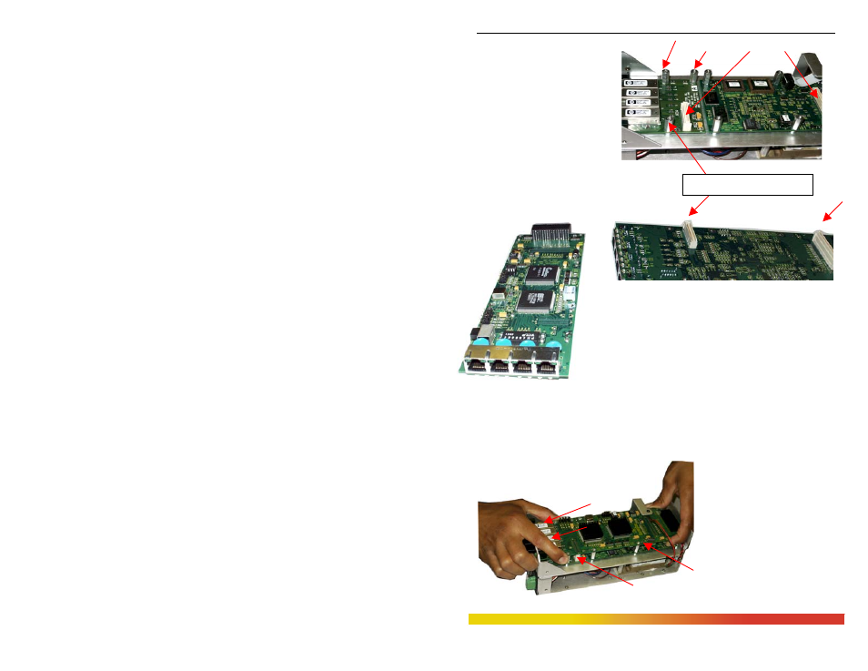
connector to hold it securely.
Fig 3.6.2c
Granddaughter Board placed
in slot & secured with three
5/16 standoff’s
Step 3. The figure here
illustrates the basic layout of an
individual PM card. Each 6KPM
card fits into the space provided on
the main board.
Fig. 3.6.2d Daughter Board, top view of
4 copper 10/100 ports
Fig 3.6.2e Daughter Board shown upside down with two
male latch connectors
Step 4. Hold the daughter board with both hands at the
end and insert the 6KPMV module inside the front
faceplate slot carefully. Then align the two cream color-
latching connectors (male) placed at the bottom of the daughter board with the other
female connector placed on the Granddaughter and main board. As shown below in Fig.
3.6.2f.
Fig. 3.6.2f Magnum 6KPM
daughter board aligned with
the bottom latch connector
after inserted properly in
front plate slot
Step 5. Once the latching
connectors are aligned properly
and the mounting holes are
aligned with stand offs then
Female latch connector