The aui port for the ethernet interface, Ethernet aui port pinouts – GE GEFanuc Automation Programmable Control Products TCP/IP Ethernet Communications for the Series 90t-70 PLC GFK-1004B User Manual
Page 218
B
B-3
GFK-1004B
Appendix B Communications Ports Characteristics
The AUI Port for the Ethernet Interface
The Ethernet Interface is equipped with an AUI port for connecting to the network. The
IEEE 802.3 AUI (Attachment Unit Interface) is standard across a variety of different
physical media. Compatible transceivers can be purchased that support 10Base5 and
10Base2 coaxial cables as well as twisted pair and fiber optic cables. The standard AUI
makes your selection of transceiver and trunk cable medium transparent to the Ethernet
Interface.
Your cables must meet the applicable IEEE 802.3 standards.
This section presents the information you need to specify the cables and related
components required for Ethernet Communications. Information in this section
includes Attachment Unit Interface (AUI) port pinouts and AUI cable diagrams.
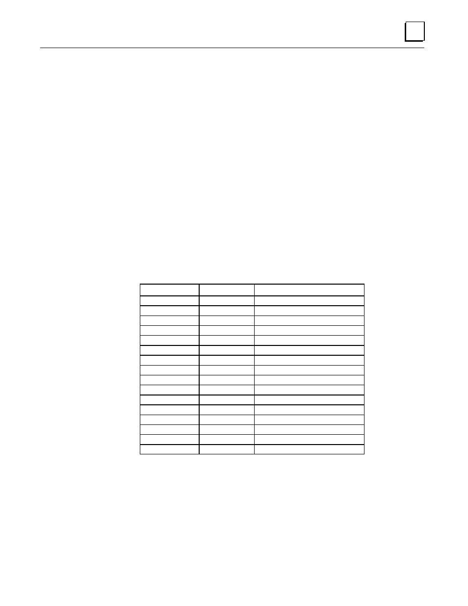
Ethernet AUI Port Pinouts
The AUI port is located on the front edge of the Ethernet Interface. This port is a 15-pin
D-type female connector. It is used to connect the Ethernet Interface to the 802.3
transceiver. Connector pinouts are shown in Table B-2.
Table B-2. Pinouts of the AUI Port
ББББББ
ББББББ
Pin Number
ББББББ
ББББББ
Signal
БББББББББББ
БББББББББББ
Description
ББББББ
1
ББББББ
GND
БББББББББББ
Signal Ground
ББББББ
ББББББ
2
ББББББ
ББББББ
CP+
БББББББББББ
БББББББББББ
Collision Presence +
ББББББ
ББББББ
3
ББББББ
ББББББ
TX+
БББББББББББ
БББББББББББ
Transmit +
ББББББ
ББББББ
4
ББББББ
ББББББ
GND
БББББББББББ
БББББББББББ
Signal Ground
ББББББ
ББББББ
5
ББББББ
ББББББ
RX+
БББББББББББ
БББББББББББ
Receive +
ББББББ
ББББББ
6
ББББББ
ББББББ
GND
БББББББББББ
БББББББББББ
Signal Ground
ББББББ
ББББББ
7
ББББББ
ББББББ
NC
БББББББББББ
БББББББББББ
Not Connected
ББББББ
ББББББ
8
ББББББ
ББББББ
GND
БББББББББББ
БББББББББББ
Signal Ground
ББББББ
ББББББ
9
ББББББ
ББББББ
CP–
БББББББББББ
БББББББББББ
Collision Presence –
ББББББ
ББББББ
10
ББББББ
ББББББ
TX–
БББББББББББ
БББББББББББ
Transmit –
ББББББ
ББББББ
11
ББББББ
ББББББ
GND
БББББББББББ
БББББББББББ
Signal Ground
ББББББ
ББББББ
12
ББББББ
ББББББ
RX–
БББББББББББ
БББББББББББ
Receive –
ББББББ
ББББББ
13
ББББББ
ББББББ
+12
БББББББББББ
БББББББББББ
+12 Volts
ББББББ
14
ББББББ
GND
БББББББББББ
Signal Ground
ББББББ
ББББББ
15
ББББББ
ББББББ
NC
БББББББББББ
БББББББББББ
Not Connected
ББББББ
ББББББ
SHELL
ББББББ
ББББББ
БББББББББББ
БББББББББББ
Chassis Ground