Gossen THERMAL GRAPHICS PRINTERS IPP 144 - 40 G User Manual
Page 14
12
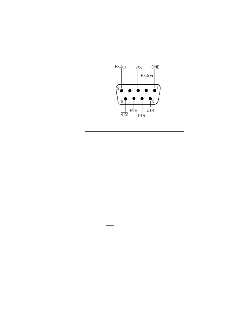
Serial
Interface I
Pin
Signal
1
GND
Ground (shield)
2
RXD (+)
Receive data
3
+5 V
Output +5 V / 20 mA
4
n.c.
5
RXD (-)
Signal ground
6
DTR
Open collector; active if
DTR is +8 V
7
DTR
(Data Terminal Ready)
+8 V: ready to receive
-7 V: not ready to receive
8
RTS
(Request To Send)
+8 V: ready to receive
-7 V: not ready to receive
(text buffer is full)
9
RTS
Open Collector; active if
RTS is +8 V
The serial interface I has been designed to allow the
implementation of all widely used interfaces:
RS 232 C; RS 422; RS 485 and Current loop.
See chapter 4.3.: Connecting diagram
This manual is related to the following products: