Fujitronic Programmable Operation Display UG520H-x User Manual
Page 79
2 - 10
Wiring
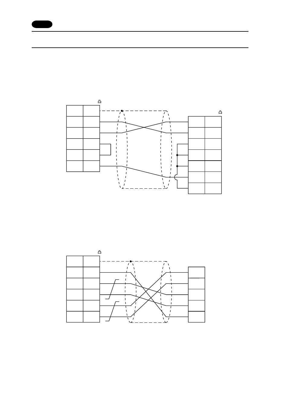
The following is a diagram to show the wiring of the cable which connects POD to PLC.
RS-232C
Wiring Diagram 1
RS-485
Wiring Diagram 2
D-sub 25pin(Male: )
FG
RD
RS
CS
SG
1
3
4
5
7
SD
RD
SD
2
RS
CS
DR
PLC
2
3
4
5
6
SG
CD
7
8
D-sub 25pin(Male: )
POD (CN1)
*
Use twist shielded cables.
D-sub 25pin(Male: )
FG
1
12
13
24
25
SDA
SDB
SG
7
RDA
RDB
SG
PLC
POD (CN1)
+SD
-SD
+RD
-RD
*
Use twist shielded cables.
4 FUJI PLC
•
4