2 fuji plc . 2, Fuji plc • 2 -4, Fuji plc • 2 – Fujitronic Programmable Operation Display UG520H-x User Manual
Page 73: Micrex-sx series)
2 - 4
FUJI PLC • 2
(MICREX-SX series)
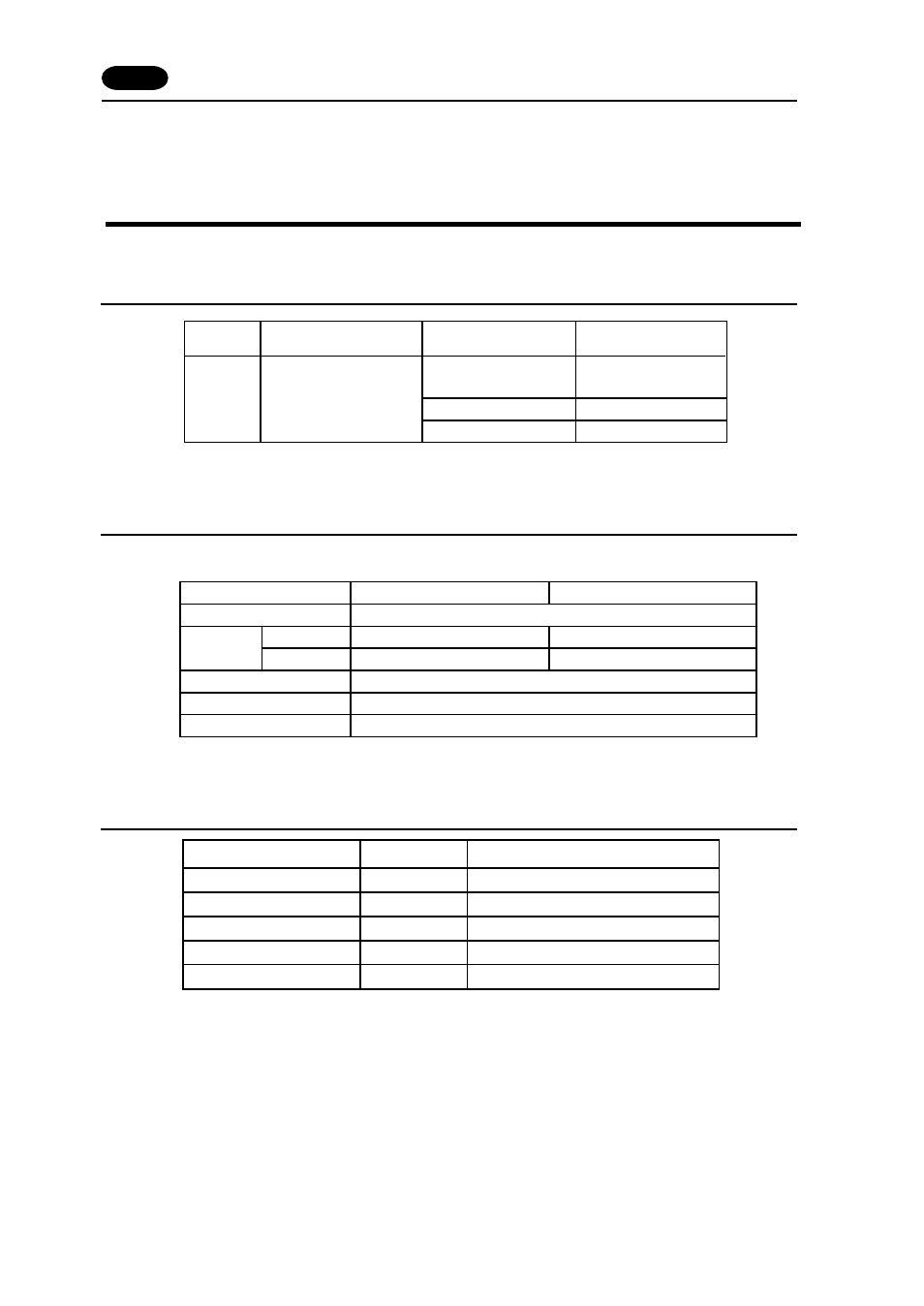
Available PLC
*
Only one unit of POD can be connected to one link unit, except for “Multi-link 2” connection.
Communication Setting
The recommended communication parameter setting of both PLC and POD is as follows:
*
No function block (FB) settings are required on the PLC.
Available Memory
To specify a memory, basically a variable name is set. For the variable name linkage function, refer to the
User’s Manual
Set the memory to the extent of the memory range of each PLC model.
Use TYPE number to assign indirect memory for macro programs.
To set an indirect memory using a macro, specify the CPU No. using the extended code.
Indirect memory setting by macro is not available for input (I) or output (Q) memory.
2
PLC
NP1L-RS2
NP1L-RS4
NP1L-RS1
RS-232C [Wiring Diagram 1]
RS-485 [Wiring Diagram 2]
RS-232C [Wiring Diagram 1]
RS-485 [Wiring Diagram 2]
Select PLC Type
MICREX-SX
Series
SPH Series
(NP1PS- x )
Wiring Diagram
Link Unit
Transmission
Control Mode
RS-232C
RS-422
Baud Rate
Parity
Data Length
Stop Bit
Item
Setting of PLC
RS-232C
RS-422
Mode 2
Mode 1
Comm. Parameter of POD
1 (fixed)
8 (fixed)
Even (fixed)
38400bps (fixed)
1 FUJI PLC
•
2
Standard Memory
TYPE
Remarks
I
(input memory)
-
O
(output memory)
-
M
(standard memory)
2
RM (retain memory)
4
SM
(system memory)
8