Fujitronic Programmable Operation Display UG520H-x User Manual
Page 167
2 - 98
35 SIEMENS PLC
•
4
Wiring
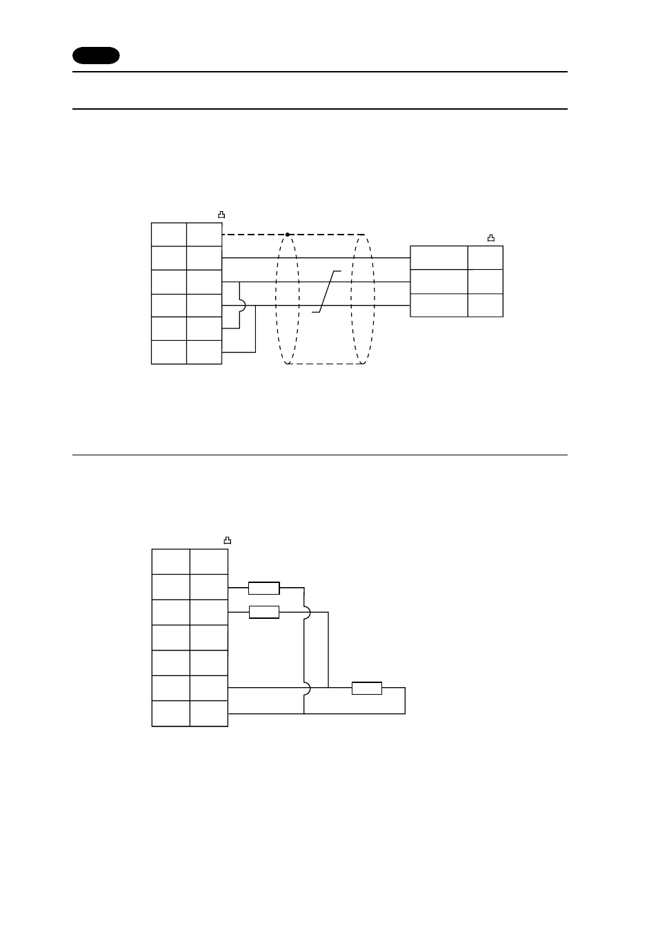
The following is a diagram to show the wiring of the cable which connects POD to PLC.
RS-422
Wiring Diagram 1
Setting of Terminal Resistance
Set the dip switch 7,8 of POD to OFF.
Connect terminal registance to the POD serial connector (CN1) as follows.
If terminal registance is not connected, the communication error may occur.
PLC
D-sub 25pin(Male: )
FG
SG
+SD
-SD
+RD
-RD
7
1
12
13
24
25
SG
TXD/RXD
TXD/RXD
5
3
8
D-sub 9pin(Male: )
*
Use twist shielded cables.
POD (CN1)
D-sub 25pin(Male: )
FG
SG
5V
+SD
-SD
+RD
-RD
7
1
9
12
13
24
25
POD (CN1)
220
Ω
390
Ω
390
Ω