N : 1 link communication (multi-link 2) – Fujitronic Programmable Operation Display UG520H-x User Manual
Page 47
1 - 38
Signal
FG
RDA
RDB
SDA
SDB
SG
Link unit
Signal
FG
RDA
RDB
SDA
SDB
SG
Link unit
SD/RD terminal resistance
(ON)
Signal
Pin No.
FG
+SD
-SD
+RD
-RD
SG
1
12
13
24
25
7
*
Use twist shielded cable.
Signal
FG
RDA
RDB
SDA
SDB
SG
Link unit
POD (CN1)
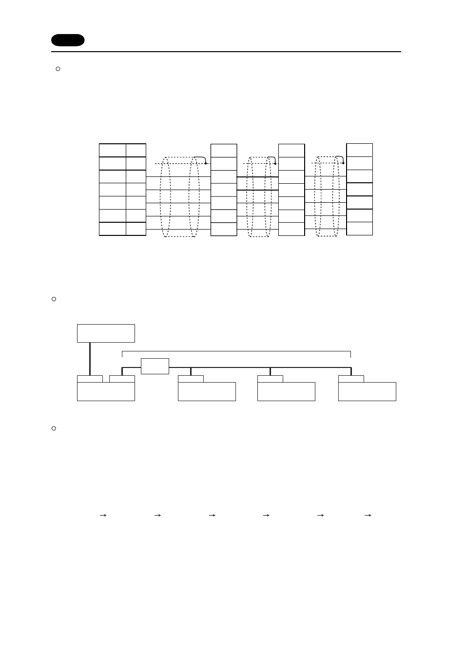
Multi-drop Communication (RS-485)
Refer to the PLC manual of each manufacturer for connection.
The following example describes how one POD is connected to three PLCs made by MITSUBISHI.
See MITSUBISHI’s manual for further details.
n : 1 Link Communication (Multi-link 2)
Up to 4 units can be connected to one PLC.
*
Between a PLC and the POD master station is the same as those for 1:1 connection.
Available PLCs for multi-link2.
As of October 2002, the PLCs supported are as follows. All the PLCs which are usable for 1:1 communi-
cation will be supported.
For the I/F driver, the Multi-Link 2 is supported by the version of 1.100 or later (screen development
software: version of 2.1.4.0 or later) and as for a POD master station, make sure the hardware version of
the unit is as follows.
As for UG221/UG220, any version can be used.
UG520H-V
4, UG520H-S
3, UG420H-V
5, UG420H-T
5, UG420H-S
4, UG320H
7
*
The Multi-Link 2 cannot be used with a communication interface unit such as UG03I-T, J, E, C, S, P,
UG02I-T, J, S.
*
The Multi-Link 2 cannot be used with Temperature controll network.
15 Connection
CN1
(a)
(c)
(b)
(e)
(d)
MJ2
CN1
CN1
CN1
PLC
Terminal
block
Communication between the stations : RS-485 (2-wire system), maximum length = 500 m
POD Master
(local Port No. 1)
POD Slave
(local Port No. 2)
POD Slave
(local Port No. 3)
POD Slave
(local Port No. 4)