32 siemens plc . 1, Siemens plc • 1 -92, Siemens plc • 1 – Fujitronic Programmable Operation Display UG520H-x User Manual
Page 161: Available plc, Communication setting
2 - 92
SIEMENS PLC • 1
(S5-90, S5-95U, S5-100U)
Available PLC
A similar program as RK512 is required.
*
1 When using [6ES5 734-1BD20] cable made by SIEMENS , connect cable of [ Wiring Diagram 2 ]
to the D-sub 25 pins side of [6ES5 734-1BD20] to communicate with POD .
Communication Setting
The recommended communication parameter setting of both PLC and POD is as follows:
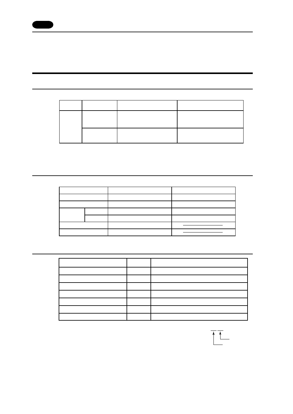
Available Memory
The assigned memory is indicated while editing
the screen as illustrated:
Set the memory to the extent of the memory range of each PLC model.
Use TYPE number to assign indirect memory for macro programs.
32
Block No.
Address No.
PLC
S5-90U
S5-95U
S5-100U
S5-95U
RS-232C [Wiring Diagram 1]
[6ES5 734-1BD20] cable made by SIEMENS
+ RS-232C [Wiring Diagram 2]
CP-521SI
(3964R Transmission Protocol)
Second serial interface
(3964R Transmission Protocol)
Select PLC Type
*
1
Link Unit
Wiring Diagram
S5
( S5 UG400 )
9600bps
Even parity
8
Baud Rate
Parity
Transmission
Code
Data Length
Stop Bit
1
Item
Setting of PLC
9600bps
Busy Signal
Hand Shake
Even
8
1
Comm. Parameter of POD
NO (fixed)
OFF (fixed)
Memory
TYPE
Remarks
DB
(data register)
0
Use memories more than DB3.
I
(input relay)
1
IW as word device
Read only
Q
(output relay)
2
QW as word device
Read only
F
(internal relay)
3
FW as word device
Read only
T
(timer/current value)
4
Read only
C
(counter/current value)
5
Read only
AS
(absolute address)
6
32 SIEMENS PLC
•
1