11 modular jack 1 & 2, Modular jack 1 & 2 -30, Modular jack 1 & 2 – Fujitronic Programmable Operation Display UG520H-x User Manual
Page 39
1 - 30
Modular Jack 1 & 2
11
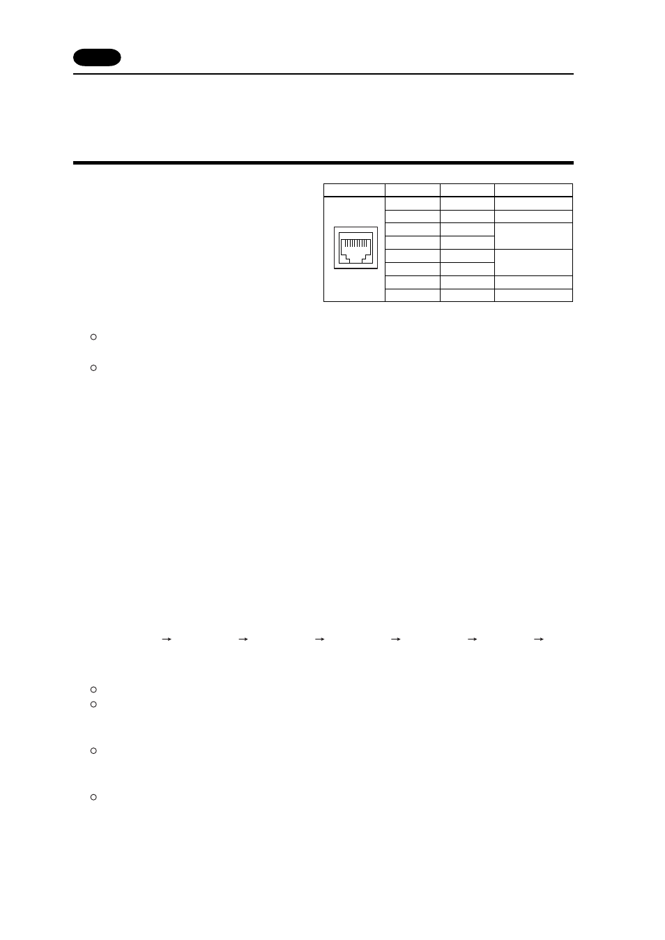
Modular Jack 1 & 2 (MJ1/2)
The right diagram is the pin arrangement and the
signal name of modular jack 1 & 2.
Setting of Modular Jack 1 & 2 (MJ1/MJ2)
Specify the use of MJ1/MJ2 by the software (UG00S-CW).
Select [Modular...] from [System Setting]. The [Modular Jack] dialog is displayed. The setting items of
[Modular Jack 1] and [Modular Jack 2] as follows.
Modular Jack 1
Modular Jack 2
[Editor port]
[Not used]
[Memory Card]
[Memory Card]
[Barcode]
[Barcode]
[UG00P-U2]
[UG00P-U2]
[Multi-Link]
*
1
*
2
[Multi-Link]
*
1
*
2
[Temp. CTRL Net]
*
2
[Temp. CTRL Net]
*
2
[UG-Link]
*
2
[UG-Link]
*
2
[Touch Switch]
[Touch Switch]
[Ladder Tool]
[Ladder Tool]
[Serial Printer]
[Serial Printer]
It is impossible to select both [Multi-Link] and [Temp. CTRL Net] in each setting of modular jack.
*
1 It is possible to select this item when [Multi-Link 2] is selected for [Connection] and [Local Port] is set
to [1] in the [Comm. Parameter] dialog.
*
2 [Multi Link 2 (master)] and [Temperature Control Network] and [UG-Link] are available in the following
hardware version or later of POD. As for UG220/UG221, any version can be used.
UG520H-V
4, UG520H-S
3, UG420H-V
5, UG420H-T
5, UG420H-S
4, UG320H
7
Editor Transferring
Use modular jack 1 (MJ1) in case of editor transferring.
When [Editor port] is selected for [Modular Jack 1] in the [P2] menu, it is also possible to transfer the
data while running, because the auto change of the local mode and the run mode is valid.
When [Editor port] is selected, on-line editing and the simulation mode are also available.
When the item other than [Editor port] is selected for [Modular Jack 1] in the [P2] menu, be sure to
transfer the data by the software in the local mode. On-line editing and the simulation mode are not
available.
When the data is transferred by software, use the cable for data transferring which is the optional
equipment made by Fuji Electric Co., Ltd. (UG00C-T: 3m) to connect POD to a personal computer.
Pin No.
1
2
3
4
5
6
7
8
MJ1/2
12345678
Signal
+SD/RD
-SD/RD
+5V
+5V
0V
0V
RD
SD
Contents
RS-485 + data
RS-485 - data
Output power supply
Max. 150mA
Signal ground
RS-232C receive data
RS-232C send data
11 Modular Jack 1
&
2