Wiring, Rs-232c wiring diagram 1, Wiring diagram 2 – Fujitronic Programmable Operation Display UG520H-x User Manual
Page 204
2 - 135
Available Memory
Direct LOGIC, Direct LOGIC(K-Sequence)
Set the memory to the extent of the memory range of each PLC model.
Use TYPE number to assign indirect memory for macro programs.
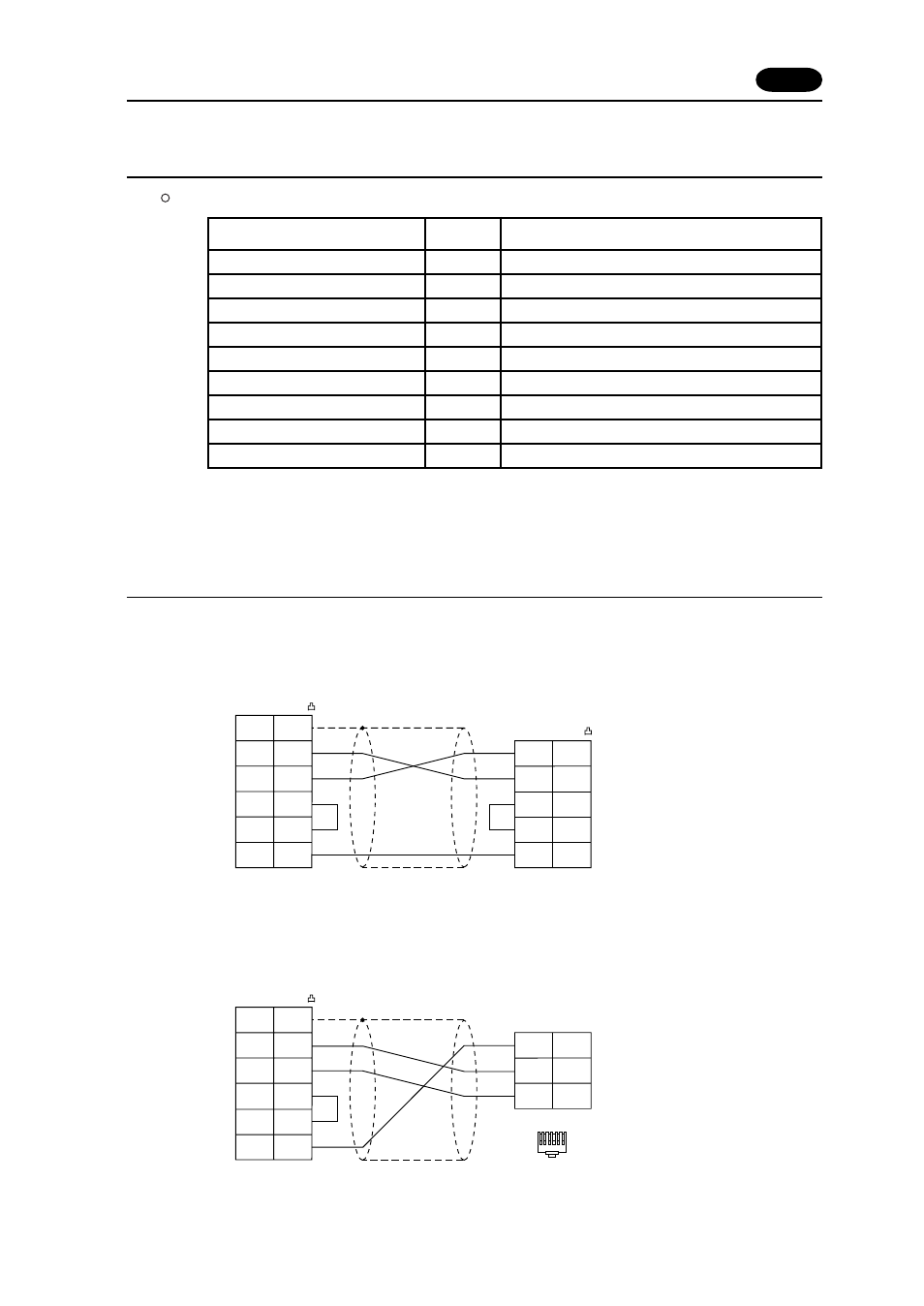
Wiring
The following is a diagram to show the wiring of the cable which connects POD to PLC.
RS-232C
Wiring Diagram 1
53 Automationdirect PLC
Memory
TYPE
Remarks
V
(data register)
0
X
(input relay)
1
Y
(output relay)
2
C
(internal relay)
3
S
(stage)
4
GX
(global inputs)
5
GY
(global outputs)
6
T
(timer/contact)
7
CT
(counter/contact)
8
POD (CN1)
D-sub 25pin(Male: )
FG
SD
RD
RS
CS
1
2
3
4
5
SD
RD
PLC
D-sub 25pin(Male: )
RS
CS
SG
2
3
4
5
7
SG
7
* Use twist shielded cables.
Wiring Diagram 2
POD (CN1)
D-sub 25pin(Male: )
Modular Connector 6pin
FG
SD
RD
SG
PLC
RxD
2
1
3
RS
4
CS
5
TxD
1
3
4
SG
7
* Use twist shielded cables.
654321