4 logic cables and connectors, Logic cables and connectors, 4 logic cables and connectors – Freescale Semiconductor Target Interface MMDS0508 User Manual
Page 18: Freescale semiconductor, inc
Con nector Info rmat ion
Logic Cables and Connectors
3–18
MMDS0508 Target Interface
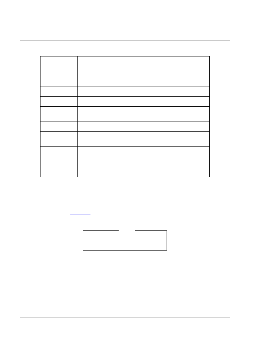
3.4 Logic Cables and Connectors
The diagram below shows the pin numbering for both pod A and pod B logic cable
connectors.
lists the pin assignments.
Table 3.1
. Serial Connector and Cable Pin Assignments
Connector Pin
Mnemonic
Signal
1
DCD
DATA CARRIER DETECT — Output signal that
indicates detection of an acceptable carrier
signal.
2
RX
RECEIVE DATA — Serial data output line.
3
TX
TRANSMIT DATA — Serial data input line.
4
DTR
DATA TERMINAL READY — Input signal that
indicates on-line/in-line/active status.
5
GND
GROUND
6
DSR
DATA SET READY — Output signal that
indicates on-line/in-line service/active status.
7
RTS
REQUEST TO SEND — Input signal that
requests permission to transfer data.
8
CTS
CLEAR TO SEND — Output signal that indicates
a ready-to-transfer data status.
19
1
•
•
•
•
•
•
•
•
•
•
•
•
•
•
•
•
•
•
•
•
20
2
Freescale Semiconductor, Inc.
For More Information: www.freescale.com