4 dsc standby screen – Furuno FS-5070 User Manual
Page 21
1. OPERATIONAL OVERVIEW
1-3
Indication Meaning
CH Channel
Tx
TX frequency (Tx: while transmitting)
Rx RX
frequency
Blinks when there are messages not read yet.
DR/DS
DR: Distress received, DS: Distress sent
Speaker on/off
SSB/TLX/AM
Class of Emission
SIMP/SDUP/DUP
Communication mode (SIMP: simplex, SDUP: semi-duplex,
DUP: full-duplex
HIGH/MID/LOW1/LOW2 Output power (LOW2: FS-5070 only, minimum output power)
FAST/SLOW/OFF
(AGC)
Auto gain control (FAST: high-speed, SLOW: low-speed, OFF: no
adjustment)
NB Noise
blanker
SQ Squelch
SEN Receiving
sensitivity
S
S-meter, displays the strength of received signal.
IA/IC/VC/RF
Transceiver unit status (IA: antenna current, IC: collector current, VC:
collector voltage, RF: PA output)
MMSI
Own ship’s ID (nine digits)
POS
Own ship’s position
EPFS/MAN
Own ship’s position data source
EPFS: GPS navigator
MAN: manual (See section 6.6.)
1.4 DSC
Standby
Screen
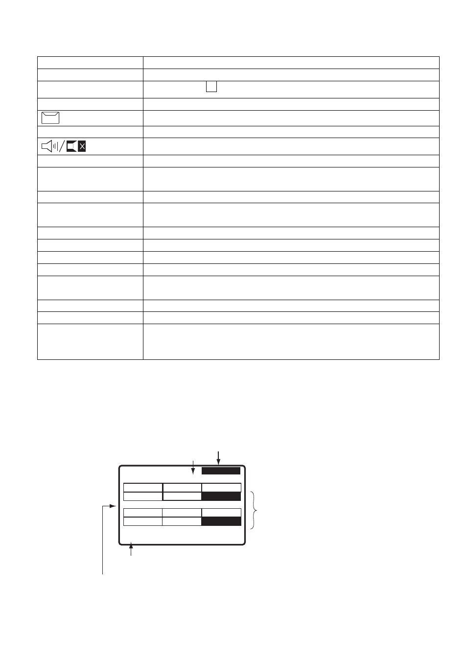
The DSC standby screen may be displayed by pressing the 6/SCAN key. This screen scans
and receives the distress and routine frequencies, and sends the acknowledgement for the
received message automatically.
WATCH KEEPING
2187.5
4207.5
6312.0
16804.5
12577.0
DISTRESS WR1
ROUTINE TRX
2177.0
4219.5
6331.0
16903.0
12657.0
8414.5
8436.5
AUTO ACK
Position and time. "EPFS" shown
when these are input automatically.
Maximum six distress and routine
frequencies scanned in clockwise
direction, and frequency currently
being scanned is highlighted.
One cycle is completed in less than
two seconds.
Acknowledge status
(AUTO ACK or MANUAL ACK)
35
°
00.0000N
UTC 00:00
135
°
00.0000E
MAN 23:59
MMSI xxxxxxxxx
Shown with nine digits.
TRX: transceiver unit
WR2: The optional antenna for the routine frequency
DSC standby screen