Fluke 5725A User Manual
Page 43
Introduction and Specifications
AC Current Specifications
1
1-27
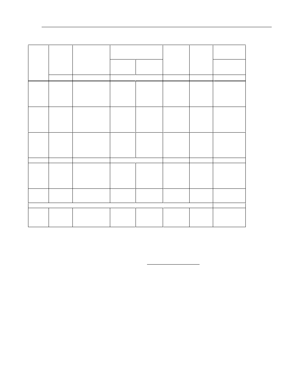
Table 1-20. AC Current Secondary Performance Specifications and Operating Characteristics
Stability
±
1 °C [Note 1]
Temperature Coefficient
[Note 2]
Compliance
Limits
Maximum
Resistive
Load
Noise and
Distortion
Range
Frequency
24 Hours
10°-40 °C
0°-10 °C and
40°-50 °C
For Full
Accuracy
[Note 3]
Bandwidth
10 Hz-50 kHz
<0.5V Burden
Hz
±
(ppm output + nA)
±
(ppm output + nA)/°C
V rms
Ω
±
(% output +
µ
A)
220
µ
A
0
10 - 20
0
20 - 40
0
40 - 1 k
0
1k - 5 k
0
5k - 10 k
150 + 5
0
80 + 5
0
30 + 3
0
50 + 20
400 + 100
0
50 + 5
0
20 + 5
00
4 + 0.5
0
10 + 1
0
20 + 100
0
50 + 5
0
20 + 5
0
10 + 0.5
0
20 + 1
0
20 + 100
7
2k
[Note 6]
0.05 + 0.1
0.05 + 0.1
0.05 + 0.1
0.25 + 0.5
0
0.5 + 1
2.2 mA
0
10 - 20
0
20 - 40
0
40 - 1 k
0
1k - 5 k
0
5k - 10 k
150 + 5
0
80 + 5
0
30 + 3
0
50 + 20
400 + 100
0
50 + 5
0
20 + 4
00
4 + 1
0
10 + 100
0
50 + 400
0
50 + 5
0
20 + 4
0
10 + 2
0
20 + 100
0
50 + 400
7
500
0.05 + 0.1
0.05 + 0.1
0.05 + 0.1
0.25 + 0.5
0
0.5 + 1
22 mA
0
10 - 20
0
20 - 40
0
40 - 1 k
0
1k - 5 k
0
5k - 10 k
150 + 50
0
80 + 50
0
30 + 30
0
50 + 500
400 + 1000
0
50 + 10
0
20 + 10
00
4 + 10
0
10 + 500
0
50 + 1000
0
50 + 10
0
20 + 10
0
10 + 20
0
20 + 400
0
50 + 1000
7
150
0.05 + 0.1
0.05 + 0.1
0.05 + 0.1
0.25 + 0.5
0
0.5 + 1
Hz
±
(ppmutput +
µ
A)
±
(ppm output +
µ
A)/°C
220 mA
0
10 - 20
0
20 - 40
0
40 - 1 k
0
1k - 5 k
0
5k - 10 k
150 + 0.5
0
80 + 0.5
0
30 + 0.3
0
50 + 3
400 + 5
0
50 + 0.05
0
20 + 0.05
00
4 + 0.1
0
10 + 2
0
50 + 5
0
50 + 0.05
0
20 + 0.05
0
10 + 0.1
0
20 + 2
0
50 + 5
7
15
0.05 + 10
0.05 + 10
0.05 + 10
0.25 + 50
0
0.5 + 100
2.2 A
20 - 1 k
1 k - 5 k
5 k - 10 k
0
50 + 5
0
80 + 20
800 + 50
00
4 + 1
0
10 + 5
0
50 + 10
0
10 + 1
0
20 + 5
0
50 + 10
1.4
[Note 4]
0.5
0.5 + 100
0.3 + 500
0
1 + 1 mA
5725A Amplifier:
±
(% output)
11 A
40 - 1 k
1 k - 5 k
5 k - 10 k
0
75 + 100
100 + 150
200 + 300
0
20 + 75
0
40 + 75
100 + 75
0
30 + 75
0
50 + 75
100 + 75
3
3
0.05
0.12
0.5
[Note 5]
Notes:
Maximum output from 5720A terminals is 2.2 A. Uncertainty specifications for 220
µ
A and 2.2 mA ranges are increased by a
factor of 1.3, plus 2
µ
A when supplied through 5725A terminals. Specifications are otherwise identical for all output locations.
1. Stability specifications are included in the Absolute Uncertainty values for the primary specifications.
2. Temperature coefficient is an adder to uncertainty specifications that does not apply unless operating more than
±
5 °C from
calibration temperature.
3. For larger resistive loads multiply uncertainty specifications by:
(
actual load
maximum load for full accuracy
)
2
4. 1.5 V compliance limit above 1 A. 5725A Amplifier may be used in range-lock mode down to 1 A.
5. For resistive loads within rated compliance voltage limits.
6. For outputs from the Aux Current terminals, the maximum resistive load for full accuracy is 1 k
Ω.
For larger resistive loads,
multiply the uncertainty as described in Note 3.
Minimum output: 9
µ
A for 220
µ
A range, 10 % on all other ranges. 1 A minimum for 5725A.
Inductive load limits: 400
µ
H (5700A/5720A, or 5725A). 20
µ
H for 5700A/5720A output >1 A.
Power factors: 5700A/5720A, 0.9 to 1; 5725A, 0.1 to 1. Subject to compliance voltage limits.
Frequency:
Range (Hz): 10.000-11.999, 12.00-119.99, 120.0-1199.9, 1.200 k-10.000 k
Uncertainty:
±
0.01 %
Resolution: 11,999 counts
Settling time to full accuracy: 5 seconds for 5700A/5720A ranges; 6 seconds for 5725A 11 A range; +1 second for amplitude
or frequency range change.
Overshoot: <10 %