Fluke 5725A User Manual
Page 35
Introduction and Specifications
Resistance Specifications
1
1-19
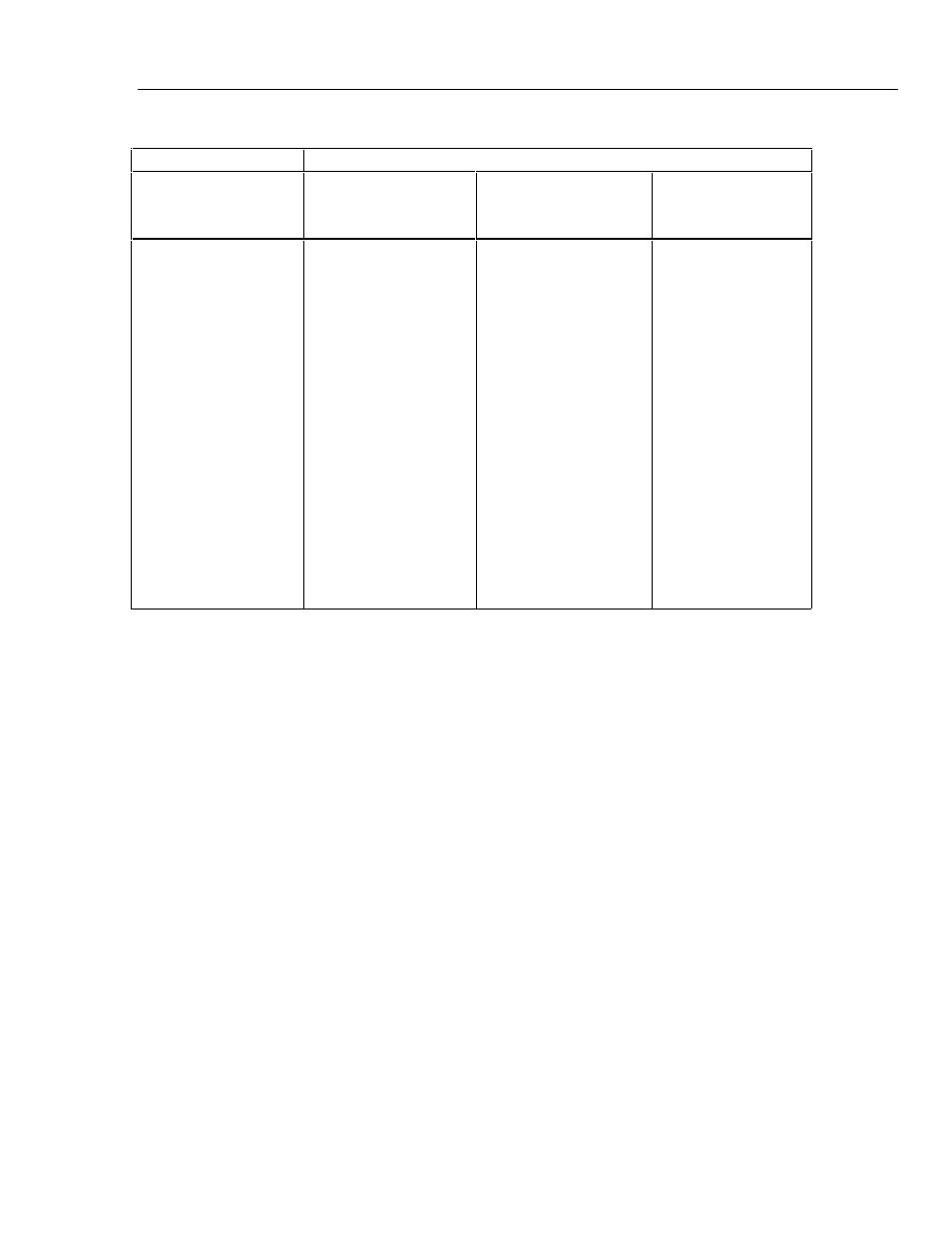
Table 1-12. Current Derating Factors
Nominal Value
Value of Derating Factor K for Over or Under Current
Ω
Two-Wire Comp
I
<
I
L
[Note 1]
Four-Wire
I
<
I
L
[Note 1]
Four-Wire
I
U
<
I
<
I
max
[Note 2]
SHORT
1
1.9
10
19
100
190
1 k
1.9 k
10 k
19 k
100 k
190 k
1 M
1.9 M
10 M
19 M
100 M
4.4
4.4
4.4
4.4
4.4
4.4
4.4
4.4
4.4
5000
5000
0.3
300
160
30
16
3.5
2.5
0.4
0.4
50
50
7.5
4.0
1.0
0.53
0.2
0.53
0.1
4 x10
-5
1.5 x 10
-4
1.6 x 10
-3
3 x 10
-3
1 x 10
-2
1.9 x 10
-2
0.1
0.19
2.0
3.8
2 x 10
-5
3.8 x 10
-5
1.5 x 10
-4
2.9 x 10
-4
1 x 10
-3
1.9 x 10
-3
Notes:
1. For
I
<
I
L
,
errors occur due to thermally generated voltages w
i
th
i
n the 5720A. Use the follow
i
ng
equat
i
on to determ
i
ne the error, and add th
i
s error to the correspond
i
ng uncerta
i
nty or stab
i
l
i
ty
spec
i
f
i
cat
i
on.
Error = K(
I
L
-
I
)/(
I
L
x
I
)
Where: Error
i
s
i
n m
Ω
for all two-w
i
re comp values and four-w
i
re short, and
i
n ppm for the rema
i
n
i
ng
four-w
i
re values.
K
i
s the constant from the above table;
I
and
I
L
are expressed
i
n mA for short to 1.9 k
Ω
;
I
and
I
L
are expressed
i
n
µ
A for 10 k
Ω
to 100 M
Ω
2. For
I
U
<
I
<
I
MAX
errors occur due to self-heat
i
ng of the res
i
stors
i
n the cal
i
brator. Use the following
equat
i
on to determ
i
ne the error
i
n ppm and add th
i
s error to the correspond
i
ng uncerta
i
nty or stab
i
l
i
ty
spec
i
f
i
cat
i
on.
Error
i
n ppm = K(
I
2
-
I
U
2
)
Where: K
i
s the constant from the above table;
I
and
I
U
are expressed
i
n mA for short to 19 k
Ω
;
I
and
I
U
are expressed
i
n
µ
A for 100 k
Ω
to 100 M
Ω