Fluke 5725A User Manual
Page 38
5725A
Instruction Manual
1-22
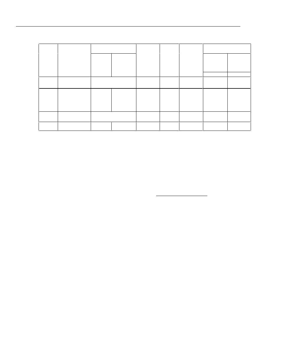
Table 1-15. DC Current Secondary Performance Specifications and Operating Characteristics
Temperature
Coefficient [Note 2]
Noise
Range
Stability
±
1 °C [Note 1]
10 °-40 °C
0 °-10 °C
and
Compliance
Limits
Burden
Voltage
Adder
[Note 3]
Maximum
Load for
Full
Accuracy
Bandwidth
0.1-10 Hz
Bandwidth
10 Hz-10 kHz
24 Hours
40 °-50 °C
[Note 4]
pk-pk
RMS
±
(ppm output
+ nA)
±
(ppm output + nA)/ °C
±
nA/V
Ω
ppm output
+ nA
nA
220
µ
A
2.2 mA
22 mA
220 mA
2.2 A
0
5 + 1
0
5 + 5
0
5 + 50
0
8 + 300
0
9 + 7
µ
A
0
1 + 0.40
0
1 + 2
0
1 + 20
0
1 + 200
0
1 + 2.5
µΑ
0
3 + 1
0
3 + 10
0
3 + 100
0
3 + 1
µ
A
0
3 + 10
µ
A
10
10
10
10
3 [Note 5]
0.2
0.2
10
100
2
µ
A
20k
2k
200
20
2
0
6 + .9
0
6 + 5
0
6 + 50
0
9 + 300
12 + 1.5
µ
A
10
10
50
500
20
µ
A
5725A
±
(ppm output
+
µ
A)
±
(ppm output +
µ
A)/
°C
ppm output
+
µ
A
µ
A
11 A
25 + 100
20 + 75
30 + 120
4
0
4
15 + 70
175
Notes:
Maximum output from the calibrator’s terminals is 2.2 A. Uncertainty specifications for 220 mA and 2.2 mA
ranges are increased by a factor of 1.3 when supplied through 5725A terminals.
1. Stability specifications are included in the Absolute Uncertainty values for the primary specifications.
2. Temperature coefficient is an adder to uncertainty specifications. It does not apply unless operating more
than
±
5 °C from calibration temperature.
3. Burden voltage adder is an adder to uncertainty specifications that does not apply unless burden voltage is
greater than 0.5 V.
4. For higher loads, multiply uncertainty specification by:
1
0.1 x actual load
maximum load for full accuracy
+
5. The calibrator’s compliance limit is 2 V for outputs from 1 A to 2.2 A. 5725A Amplifier may be used in range-
lock mode down to 0 A.
Minimum output: 0 for all ranges, including 5725A.
Settling time to full accuracy: 1 second for mA and mA ranges; 3 seconds for 2.2 A range; 6 seconds for 11 A
range; + 1 second for range or polarity change
Overshoot: <5 %